- Remember me Not recommended on shared computers
Forgot your password?
- Maintenance & D.Y.I.

2010 Journey Starter Location/ Replacement
By bc1987 June 22, 2017 in Maintenance & D.Y.I.
- Reply to this topic
- Start new topic
Recommended Posts
I've been having issues starting my 2010 Journey ( 2WD 6 cyl , 3.5 L, Automatic 6 -spd) and I'm convinced it may be a bad starter. I replaced the battery in January and just replaced the alternator a few days ago after my car would not start and a horrible smell permeated through the vents when attempting to start multiple times. New alternator is in and now when I turn the key to attempt to start the engine , I get nothing, no sounds whatsoever. Lights are on and do not dim when attempting to start. Can anyone advise where exactly the starter is located? I have not been able to find the location of the starter and have not found any indication of where it may be online. Any help would be much appreciated. Pictures of starter location would be even better.
Link to comment
Share on other sites.
- 2 weeks later...
Try putting the vehicle in neutral and then start it. If it starts it may be the neutral safety switch which is inside the transmission causing the problem.
- jkeaton and 2late4u

9 hours ago, srk23 said: Try putting the vehicle in neutral and then start it. If it starts it may be the neutral safety switch which is inside the transmission causing the problem.
check you wire connections for loose or corroded at the starter and frame some have found that to be their problems... good luck
Join the conversation
You can post now and register later. If you have an account, sign in now to post with your account. Note: Your post will require moderator approval before it will be visible.

× Pasted as rich text. Paste as plain text instead
Only 75 emoji are allowed.
× Your link has been automatically embedded. Display as a link instead
× Your previous content has been restored. Clear editor
× You cannot paste images directly. Upload or insert images from URL.
- Insert image from URL
- Submit Reply
- Existing user? Sign In
More Forum Apps
- Online Users
- Leaderboard
|| Forum Activity ||
- All Activity
- Create New...

Home » Troubleshooting » Dodge Journey won’t start – causes and how to fix it
Dodge Journey won’t start – causes and how to fix it
Dodge Journey is a reliable road companion, but its a machine with hundreds of interconnected parts, and like any other machine it sometimes fail to deliver normal operation. In this article we go through most common causes of Journey breakdown and how you can fix the problem.
The most common causes that hinders normal starting operation of your Journey are dead 12v battery, corrosion on battery terminals, and dead key fob battery. However, bad alternator, clogged fuel filter, broken starter, blown fuse, empty gas tank, immobilizer error, or any fault in the electrical system can also cause your vehicle not to start.
1. Weak Battery
If your Journey’s engine won’t crank or cranks very slowly, then the most likely culprit is weak or dead 12v battery. Investigating more closely and doing a battery voltage test will clarify whether the starting problem is due to the battery. A test can be done to measure the voltage between the battery poles, check the acid level and assess the condition of the starter battery.
If a new car battery has been installed, the battery may not have yet reached its full capacity. There is nothing to worry about. A new battery only develops its full capacity over time.
Test 12v battery
The voltage of the battery on your Dodge Journey can be measured precisely with a multimeter. Before the test, the multimeter is set to the voltage range of the battery and connected to its plus and minus poles. Successful testing of the car battery, i.e. checking the voltage, usually results in values of approx. 12 to 13 volts. Values above 14 or below 11.5 volts require an expert assessment of the condition of the car battery. Because the battery may have a defect with these measured values and must be replaced.
Jump start Dodge Journey
If dead battery is the reason for the breakdown of your Journey, you can easily jump start it using jumper cables and a healthy battery from another vehicle, or using a battery booster if available.
First connect red cable to the positive terminal of your Journey’s dead battery, then to the positive terminal of donor battery. Next connect black cable to the negative terminal of donor battery, then to the bare metal in the engine bay of your Journey. Start the donor vehicle and then your Journey. Remove the cables in reverse order.

2. Corrosion on battery
Corrosion on the contacts of your car battery leads to loss of contact and reduced current flow, which means that your engine can no longer start properly.
To know if your Journey’s starting problems are from dirty battery contacts, you need to investigate them. If you lift the rubber covers over the two battery terminals, you can check the terminals for corrosion. If you discover white deposits or silvery-green deposits, but no further cracks or damage, you do not have to replace the battery, just clean it.
Clean battery corrosion
To clean the battery on your Dodge Journey, you have to remove the pole cables first, which requires no special knowledge, just a little concentration, as the order is very important. First remove the black cable from the negative pole. If the pole clamp is very tight, you can open it with pliers. We advise against using metal pliers, but if you use them, you must make sure that you do not touch any other parts of the body. Next you can unplug the red positive pole cable. Once the battery has been removed from the circuit, you can start cleaning the corroded battery. After cleaning, reconnect the terminals.
3. Weak key fob battery
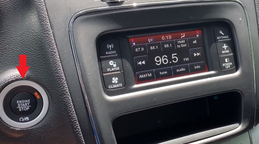
If your Journey has push start/stop button, then its possible that your vehicle may not start due to weak key fob battery. Don’t worry, you can still start your vehicle – the battery is only used to send the signal for locking/unlocking. If the key fob battery is empty, the door no longer locks or unlocks at the push of a button. The doors must then be opened manually. The immobilizer is controlled by a passive transponder. Passive means, among other things, that the transponder in the key does not need its own power source.
How to start Dodge Journey with dead key fob battery
If you have a model of Journey which only has a key fob with start/stop button and no place to insert a key, then try placing your key fob as close to the start/stop button as you can and then start the vehicle.
Tip: You can try starting your Journey with its second key. It will also rule out any other problem with the first key, for example, water damage.
4. Broken starter motor
A starter is a motor for starting the engine of your Journey. The average life of a starter motor is about 100,000 to 150,000 miles, and the life will be shortened if the engine is started more frequently. In any case, since the starter motor also has a limited life, it will break down after using the car for a long time, and if the starter motor breaks down, the engine will not start.
Symptom: When you turn the key to start the engine of your Journey, you will hear a clicking sound, which is the sound of a bad starter motor. And if the starter motor does not work with a healthy battery, suspect a malfunction of the starter.
If the starter fails, it usually needs to be replaced with a new one.
Temporary fix for starter
If the engine does not start due to the starter, the engine may start if you turn the key while hitting the starter motor with something like a stick or metal tool. This workaround is effective when the parts inside the starter are stuck together or the gears are slightly out of alignment.
However, it is possible that the starter is nearing the end of its life, so it is recommended that you have it inspected at a dealer or maintenance shop.
5. Defective alternator
An alternator is a generator that produces electricity. If your Journey’s alternator fails, it will not be able to produce electricity and the battery will not be able to charge. Therefore, even if you think that the cause of the engine not starting is a battery failure and replace the battery, the battery will soon run out and the engine will not start.
Alternators rarely break down. In particular, modern cars have improved performance, so it is said that they will last 200,000 to 300,000 miles. Still, it can break down depending on how you use it, and in the case of a used car, the alternator may be quite old. Don’t let your guard down.
If the alternator breaks down, it must be replaced with a new alternator.
6. Clogged fuel filter
The fuel filter of your Journey does not wear out like a mechanical part, but it gets clogged by dirt and airborne particles and clogs over time. The permeability of the filter drops, and so does the fuel pressure. To a certain extent this doesn’t matter, but if the fuel filter is too dirty, the engine will no longer perform at full capacity and in some instance may not start at all. Cleaning is not possible, you can only change the filter.
7. Fuel pump failure
If your Journey’s fuel pump fails, then the engine won’t start. The pump normally ensures that the necessary amount of fuel is passed from the tank to the injection system of the engine with sufficient pressure.
Before your fuel pump stops working, it usually becomes noticeable: if your car’s engine breaks down from time to time, the car is difficult to start, the engine jerks a little or the engine performance drops, you should have your pump checked.
Wear or contamination of the pump can be the reason for this. If the pump is leaking, a power contact is broken, a line or a pump lever is broken, the fuel pump is usually also noticeable before failure. You can have a defective fuel pump replaced in your workshop.
8. Blown fuse
In rare cases, a blown fuse could also be the culprit in the breakdown of your Journey. Check all fuses in the fuse box essential for starting the engine. But, be careful when lending a hand yourself to the fuse box! The box is under power and repairs or tests should always be done in a workshop.
9. Defective spark plugs
Without functioning spark plugs, the engine will not start. The spark plugs themselves are often not affected by a defect. Instead, plug connections on the ignition system come loose. If only one plug is actually loose, you can fix the problem yourself on site. If a spark plug has failed, it must be replaced in the workshop.
10. Rodent damage
Rodent damage can be another reason why your Dodge Journey won’t start. The animals crawl under the vehicle and bite through cables and wires. In principle, this can affect all vehicle systems such as the fuel supply, the oil supply or the power supply.
The rodent damage can usually be seen quickly by looking into the engine compartment. The damage caused by the rodent bite can be repaired in the workshop. Be prepared for relatively high costs here.
11. Engine failure
Although very rare, but it can also be the cause of the breakdown of your Journey. If a vehicle has an engine failure, then nothing works anymore. It is not uncommon for the driver of a vehicle to be responsible for such damage. Typical causes include tearing of the timing belt, incorrect fueling, insufficient oil, hydrolock, overheating of the engine, or continuous driving in an excessive speed range.

Only an experienced mechanic can diagnose engine failure in a workshop.
Use OBD2 scanner for diagnosis
Since Dodge Journey is equipped with on-board diagnostics (OBD), a fault diagnosis can provide initial indications of where the malfunction is located.
To begin troubleshooting, you must first connect the diagnostic tool to your Journey. The OBDII connector is usually located under the dashboard. With the wire connected, you should turn the ignition on. But be careful not to start the engine. Most diagnostic devices then ask for some information about the vehicle. It is important that you enter this 100% correctly, otherwise the result of the search may be falsified. In addition to the vehicle manufacturer and model, you usually also have to type in the engine and vehicle ID number. For exact troubleshooting, always check whether the information is correct.
There are many reasons why your Journey may not start. When looking for the trigger, you should always start with the most obvious cause, the empty battery.
In any case, it is advisable for laypersons to call a breakdown service or a workshop. In the event of a defect, the latter can directly initiate the repair.

4 thoughts on “ Dodge Journey won’t start – causes and how to fix it ”

My Dodge Journey will not start after driving a short time, and then stopping about 20 minutes, then try to start, press lock unlock wait 10 minutes, car will then start every time.

This is a problem I am having with my Dodge Journey as well. I haven’t had this SUV 3 years and I am still paying on it.

My 2017 Dodge Journey ran fine in the morning yesterday, was totally dead last night – no locks, no dash lights, no power button. Long story short – disconnected + positive cable under hood to reset computer. Put cables back on after 10 min wait – got feeble spark while attaching wires. Entered car, found 4-way flashers indicating on dash. Button was accidentally depressed after morning drive. Charged battery for 1 hour with battery charger. Started fine, but needed to be driven extensively to fully charge 69-month old battery. Buying new battery tomorrow.

My dodge journey 2014 is not starting. It was stripped for overheating but now after the reassemble it’s not starting, VIN initialising and press clutch to start engine are showing on the clock
- Lexus ES makes clicking noise and won’t start – causes and how to fix it
- Cadillac SRX shakes at highway speeds – causes and how to fix it
- Renault Scenic makes grinding noise when starting – common causes
- How to remote start Hyundai Elantra with key fob or mobile device
- Audi A6 key fob not working – causes and how to fix it
- Infiniti QX50 steering wheel controls not working – causes and how to fix it
- Is Chevy HHR key fob waterproof?
- VW Jetta windshield washer not working – causes and how to fix it
- Ram ProMaster door makes a squeaking noise when opening or closing
- Range Rover Velar low AC refrigerant symptoms, how to recharge
- Dodge Charger airbag light is on – causes and how to reset
- Jaguar XJ airbag light is on – causes and how to reset
- Fiat 124 Spider shakes at highway speeds – causes and how to fix it
- Nissan Maxima makes humming noise at high speeds – causes and how to fix it
- Volvo S60 steering wheel controls not working – causes and how to fix it
- Chevy Blazer heater not working – causes and diagnosis
- How to operate climate control on BMW 3-Series
- Maserati Quattroporte burning smell causes and how to fix it
- VW Jetta dirty cabin air filter symptoms, when to replace
- Buick Encore ABS light is on – causes and how to reset

- Dodge Manuals
- 2010 Journey
- Owner's manual
Dodge 2010 Journey Owner's Manual
- User manual (96 pages)
- User manual (88 pages)
- Manual (504 pages)
- page of 512 Go / 512
Table of Contents
- Troubleshooting
Introduction 1
- Introduction
- How to Use this Manual
- Warnings and Cautions
- Vehicle Identification Number
- Vehicle Modifications/Alterations
Things to Know before Starting Your Vehicle
- Wireless Ignition Node (WIN)
- Tip Start Feature
- Removing Key FOB from Ignition
- Key-In-Ignition Reminder
- Things to Know before Starting Your Vehicle 9
- Replacement Keys
- Customer Key Programming
- General Information
- Rearming of the System
- To Arm the System
- To Disarm the System
- Illuminated Entry
- To Unlock the Doors and Liftgate
- To Lock the Doors and Liftgate
- Using the Panic Alarm
- Remote Open Window Featuree
- Programming Additional Transmitters
- Transmitter Battery Replacement
- How to Use Remote Start
- Manual Door Locks
- Power Door Locks
- Child Protection Door Lock System (Rear Doors)
- Power Windows
- Wind Buffeting
- Lap/Shoulder Belts
- Lap/Shoulder Belt Untwisting Procedure
- Automatic Locking Retractors (ALR) Mode - if Equipped
- Seat Belt Pretensioners - if Equipped
- Supplemental Active Head Restraints (AHR)
- Enhanced Seat Belt Use Reminder System (Beltalert )
- Seat Belt Extender
- Seat Belts and Pregnant Women
- Supplemental Restraint System (SRS) - Airbags
- Advanced Front Airbag Features
- Airbag Deployment Sensors and Controls
- Event Data Recorder (EDR)
- Child Restraints
- Engine Break-In Recommendations
- Transporting Passengers
- Exhaust Gas
- Safety Checks You Should Make Inside the Vehicle
- Periodic Safety Checks You Should Make Outside the Vehicle
Understanding the Features of Your Vehicle
- Inside Day/Night Mirror
- Automatic Dimming Mirror - if Equipped
- Outside Mirrors
- Outside Mirrors Folding Feature - if Equipped
- Power Mirrors
- Heated Mirrors - if Equipped
- Illuminated Vanity Mirrors - if Equipped
- Manual Front Seat Adjustments
- Recliner Adjustment
- Lumbar Support - if Equipped
- Driver's Seat Height Adjustment - if Equipped
- Fold Flat Front Passenger Seat - if Equipped
- Adjusting Active Head Restraints
- Second Row Passenger Seats
- Third Row Passenger Seats - Seven Passenger Models
- Heated Seats - if Equipped
- 60/40 Split Second-Row Passenger Seats
- 50/50 Split Third-Row Passenger Seats with Fold-Flat Feature - Seven Passenger Models
- Uconnect™ Phone - if Equipped
- Voice Command - if Equipped
- To Open and Close the Hood
- Multifunction Lever
- Headlights and Parking Lights
- Automatic Headlights - if Equipped
- Headlight Time Delay - if Equipped
- Headlights with Wipers (Available with Automatic Headlights Only)
- Instrument Panel Dimmer
- Daytime Running Lights - if Equipped
- Fog Lights - if Equipped
- Lights-On Reminder
- Turn Signals
- Flash-To-Pass
- High/Low Beam Switch
- Battery Saver Feature
- Cargo Light
- Lane Change Assist
- Windshield Wiper Operation
- Intermittent Wiper System
- Windshield Washers
- Mist Feature
- Tilt/Telescoping Steering Column - if Equipped
- To Activate
- To Set a Desired Speed
- To Deactivate
- To Resume Speed
- To Vary the Speed Setting
- To Accelerate for Passing
- Turning Parkview on or off - with Navigation/Multimedia Radio
- Turning Parkview on or off - Without Navigation/Multimedia Radio
- Courtesy/Reading Lights
- Sunglasses Storage
- Interior Observation Mirror
- Power Sunroof Switch - if Equipped
- Programming Homelink
- Gate Operator/Canadian Programming
- Using Homelink
- Reprogramming a Single Homelink Button
- Troubleshooting Tips
- Opening Sunroof - Manually
- Opening Sunroof - Express
- Closing Sunroof - Manually
- Closing Sunroof - Express
- Pinch Protect Feature
- Pinch Protect Override
- Venting Sunroof - Express
- Sunshade Operation
- Sunroof Maintenance
- Ignition off Operation
- Sunroof Fully Closed
- Electrical Power Outlets
- Power Inverter - if Equipped
- Instrument Panel Storage Compartment - if Equipped
- Console Storage
- Flip 'N Stow™ Front Passenger Seat Storage - if Equipped
- Second-Row Passenger Seat Temporary Storage bin
- Second-Row Map Pocket and Grocery Retainers - if Equipped
- In-Floor Storage bin with Removable Liner
- Chill Zone Beverage Cooler Operation
- Rechargeable Flashlight - if Equipped
- Cargo Management System
- Rear Window Wiper/Washer
- Rear Window Defroster
- Roof Luggage Rack - if Equipped
Understanding Your Instrument Panel
- Instrument Panel Features
- Instrument Cluster
- Instrument Cluster Descriptions
- CMTC Reset Buttons
- Compass/Temperature Display
- Electronic Vehicle Information Center (EVIC) Displays
- Oil Change Required
- Trip Functions
- Compass Display / ECO (Fuel Saver Mode) - if Equipped
- Personal Settings (Customer-Programmable Features)
- Media Center 230 (REQ) - AM/FM Stereo Radio and 6-Disc CD/DVD Changer (MP3/WMA AUX Jack)
- Operating Instructions - Radio Mode
- Operation Instructions - (Disc Mode for CD and MP3/WMA Audio Play, DVD-Video)
- Notes on Playing MP3/WMA Files
- List Button (Disc Mode for MP3/WMA Play)
- Info Button (Disc Mode for MP3/WMA Play)
- Operation Instructions - CD Mode for CD and MP3 Audio Play
- Notes on Playing MP3 Files
- Operation Instructions - Auxiliary Mode
- List Button (CD Mode for MP3 Play)
- Info Button (CD Mode for MP3 Play)
- Operating Instructions - Uconnect™ Phone
- Clock Setting Procedure
- System Activation
- Electronic Serial Number/Sirius Identification Number (ESN/SID)
- Selecting Uconnect™ Multimedia (Satellite) Mode
- Satellite Antenna
- Reception Quality
- Operating Instructions - Uconnect™ Multimedia (Satellite) Mode
- Operating Instructions - Uconnect™ Phone (if Equipped)
- Operating Instructions - Video Entertainment System (VES)™ (if Equipped)
- Uconnect™ Multimedia (Sirius Backseat TV™) - if Equipped
- Video Entertainment System (VES)™ - if Equipped
- Connecting the Ipod Device
- Controlling the Ipod Using Radio Buttons
- List or Browse Mode
- Right-Hand Switch Functions
- Left-Hand Switch Functions for Radio Operation
- Left-Hand Switch Functions for Media (I.e., CD) Operation
- CD/DVD Disc Maintenance
- Manual Heating and Air Conditioning System
- Three-Zone Manual Air Conditioning and Heating Systems - if Equipped
- Two- and Three-Zone Automatic Temperature Control (ATC) Systems - if Equipped
- Operating Tips
- Radio Operation and Cellular Phones
Starting and Operating
- Automatic Transmission
- Normal Starting (Tip Start)
- Extreme Cold Weather (below 20°F or 29°C)
- If Engine Fails to Start
- After Starting
- Engine Block Heater - if Equipped
- Key Ignition Park Interlock
- Brake/Transmission Interlock System
- Automatic Transmission Ignition Interlock System
- Four-Speed or Six-Speed Automatic Transmission
- Gear Ranges
- All Wheel Drive (AWD) - if Equipped
- Acceleration
- Flowing/Rising Water
- Power Steering Fluid Check
- Parking Brake
- Anti-Lock Brake System (ABS)
- Brake Assist System (BAS)
- Traction Control System (TCS)
- Electronic Roll Mitigation (ERM)
- Electronic Stability Program (ESP)
- ESP/BAS Warning Light and ESP/TCS Indicator Light
- Trailer Sway Control (TSC)
- Tire Markings
- Tire Terminology and Definitions
- Tire Loading and Tire Pressure
- Tire Pressure
- Tire Inflation Pressures
- Radial-Ply Tires
- Compact Spare Tire
- Tire Spinning
- Tread Wear Indicators
- Life of Tire
- Replacement Tires
- Tire Chains
- Tire Rotation Recommendations
- Base System
- Premium System - if Equipped
- 2.4L Engine
- Reformulated Gasoline
- Gasoline/Oxygenate Blends
- MMT in Gasoline
- Materials Added to Fuel
- Fuel System Cautions
- Carbon Monoxide Warnings
- Fuel Filler Cap (Gas Cap)
- Loose Fuel Filler Cap Message
- Vehicle Certification Label
- Gross Vehicle Weight Rating (GVWR)
- Gross Axle Weight Rating (GAWR)
- Overloading
- Common Towing Definitions
- Trailer Hitch Classification
- Trailer Towing Weights (Maximum Trailer Weight Ratings)
- Trailer and Tongue Weight
- Towing Requirements
- Towing Tips
- Towing this Vehicle Behind Another Vehicle
Advertisement
Quick Links
- Introduction 1 4
- Things to Know before Starting Your Vehicle 10
- Understanding the Features of Your Vehicle 90
- Understanding Your Instrument Panel 178
- Starting and Operating 292
- What to Do in Emergencies 380
- Maintaining Your Vehicle 402
- If You Need Consumer Assistance 478
Related Manuals for Dodge 2010 Journey

Summary of Contents for Dodge 2010 Journey
- Page 1 Journey 2 0 1 0 O W N E R ’ S M A N U A L...
Page 2: Introduction
Page 4: table of contents, page 5: introduction.
- Page 6 INTRODUCTION 5...
Page 7: Vehicle Identification Number
Page 8: vehicle modifications/alterations.
- Page 10 THINGS TO KNOW BEFORE STARTING YOUR VEHICLE CONTENTS A Word About Your Keys ....12 Wireless Ignition Node (WIN) ... . 12 Key FOB .
- Page 11 10 THINGS TO KNOW BEFORE STARTING YOUR VEHICLE Using The Panic Alarm ....23 Remote Open Window Featuree ... 23 Programming Additional Transmitters .
- Page 12 Seat Belts And Pregnant Women ..53 Seat Belt Extender ..... 53 Supplemental Restraint System (SRS) —...
Page 13: Things To Know Before Starting Your Vehicle 9
Page 14: key fob, page 15: tip start feature, page 16: key-in-ignition reminder, page 17: replacement keys, page 18: customer key programming, page 19: to disarm the system, page 20: remote keyless entry (rke), page 21: to unlock the doors and liftgate.
- Page 22 Flash Lights with Remote Key Lock This feature will cause the turn signal lights to flash when the doors are locked or unlocked with the RKE transmit- ter. This feature can be turned on or turned off. To change the current setting, proceed as follows: •...
Page 23: To Lock The Doors And Liftgate
Page 24: using the panic alarm, page 25: transmitter battery replacement, page 26: general information.
- Page 27 26 THINGS TO KNOW BEFORE STARTING YOUR VEHICLE • Hood closed • Liftgate closed • HAZARD switch off • BRAKE switch inactive (brake pedal not pressed) • Ignition key removed from ignition switch • Battery at an acceptable charge level, and •...
- Page 28 • For security, power window and power sunroof op- eration (if equipped) are disabled when the vehicle is in the Remote Start mode. • The engine can be started two consecutive times (two 15-minute cycles) with the RKE transmitter. However, the ignition switch must be cycled to the ON position before you can repeat the start sequence for a third cycle.
Page 29: Door Locks
Page 30: power door locks.
- Page 31 30 THINGS TO KNOW BEFORE STARTING YOUR VEHICLE To prevent you from locking your Key Fob in the vehicle, the power door lock switch will not operate when the Key Fob is in the ignition and either front door is open. A chime will sound as a reminder to remove the Key Fob.
- Page 32 5. The doors were not previously unlocked 6. The vehicle speed is 0 mph (0 km/h). Automatic Unlock Doors on Exit Programming The Automatic Unlock Doors On Exit feature can be enabled or disabled as follows: • For vehicles equipped with the EVIC, refer to “Elec- tronic Vehicle Information Center (EVIC)/Personal Settings (Customer-Programmable Features)”...
Page 33: Child Protection Door Lock System (Rear Doors)
- Page 34 WARNING! Avoid trapping anyone in a vehicle in a collision. Remember that the rear doors can only be opened from the outside when the child protection locks are engaged. Failure to follow this warning may result in serious injury or death. NOTE: •...
Page 35: Windows
- Page 36 NOTE: • For vehicles not equipped with the Electronic Vehicle Information Center (EVIC), the power window switches will remain active for 45 seconds after the ignition switch is turned to the LOCK position. Open- ing either front door will cancel this feature. •...
- Page 37 36 THINGS TO KNOW BEFORE STARTING YOUR VEHICLE Auto-Up Feature with Anti-Pinch Protection — If Equipped On some models, the driver’s and front passenger’s power window switch has an Auto-up feature. Pull the window switch up to the second detent, release, and the window will go up automatically.
Page 38: Wind Buffeting
Page 39: liftgate, page 40: occupant restraints.
- Page 41 40 THINGS TO KNOW BEFORE STARTING YOUR VEHICLE • All seat belt systems (except the driver’s) include Automatic Locking Retractors (ALRs), which lock the seat belt webbing into position by extending the belt all the way out and then adjusting the belt to the desired length to restrain a child seat or secure a large item in a seat —...
Page 42: Lap/Shoulder Belts
- Page 43 42 THINGS TO KNOW BEFORE STARTING YOUR VEHICLE WARNING! (Continued) • Wearing your belt in the wrong place could make your injuries in a collision much worse. You might suffer internal injuries, or you could even slide out of part of the belt. Follow these instructions to wear your seat belt safely and to keep your pas- sengers safe, too.
- Page 44 3. When the belt is long enough to fit, insert the latch plate into the buckle until you hear a “click.” Connecting Latch Plate To Buckle THINGS TO KNOW BEFORE STARTING YOUR VEHICLE 43 WARNING! • A belt that is buckled into the wrong buckle will not protect you properly.
- Page 45 44 THINGS TO KNOW BEFORE STARTING YOUR VEHICLE WARNING! (Continued) • A belt that is worn under your arm is dangerous. Your body could strike the inside surfaces of the vehicle in a collision, increasing head and neck injury. A belt worn under the arm can cause internal injuries.
- Page 46 WARNING! • A lap belt worn too high can increase the risk of internal injury in a collision. The belt forces won’t be at the strong hip and pelvic bones, but across your abdomen. Always wear the lap belt as low as possible and keep it snug.
Page 47: Lap/Shoulder Belt Untwisting Procedure
Page 48: automatic locking retractors (alr) mode - if equipped, page 49: supplemental active head restraints (ahr).
- Page 50 Active Head Restraint (AHR) Components 3 — Head Restraint Back Half 1 — Head Restraint Front Half (Decorative Plastic Rear (Soft Foam and Trim) Cover) 4 — Head Restraint Guide 2 — Seatback Tubes THINGS TO KNOW BEFORE STARTING YOUR VEHICLE 49 CAUTION! All occupants, including the driver, should not oper- ate a vehicle or sit in a vehicle’s seat until the head...
- Page 51 50 THINGS TO KNOW BEFORE STARTING YOUR VEHICLE 1. Grasp the deployed AHR from the rear seat. Hand Positioning Points On AHR 2. Position the hands on the top of the deployed AHR at a comfortable position. 3. Pull down then rearward towards the rear of the vehicle then down to engage the locking mechanism.
- Page 52 3 — Final Downward Movement To Engage Locking Mecha- nism 4. The AHR front soft foam and trim half should lock into the back decorative plastic half. THINGS TO KNOW BEFORE STARTING YOUR VEHICLE 51 AHR In Reset Position NOTE: •...
Page 53: Enhanced Seat Belt Use Reminder System (Beltalert )
Page 54: seat belts and pregnant women, page 55: supplemental restraint system (srs) - airbags.
- Page 56 The Advanced Front Airbags have a multistage inflator design. This allows the airbag to have different rates of inflation based on the severity and type of collision. This vehicle may be equipped with driver and/or front passenger seat track position sensors that may adjust the inflation rate of the Advanced Front Airbags based upon seat position.
Page 57: Advanced Front Airbag Features
- Page 58 WARNING! (Continued) • Do not put anything on or around the airbag covers or attempt to open them manually. You may damage the airbags and you could be injured because the airbags may no longer be functional. The protective covers for the airbag cushions are designed to open only when the airbags are inflat- ing.
- Page 59 58 THINGS TO KNOW BEFORE STARTING YOUR VEHICLE deploys independently, that is a left side impact deploys the left airbag only and a right-side impact deploys only the right airbag. Supplemental Side Airbag Inflatable Curtain (SABIC) — If Equipped SABIC airbags may offer side-impact and vehicle rollover protection to front and rear seat outboard occupants in addition to that provided by the body structure.
- Page 60 The system includes side impact sensors adjacent to both front and rear seat occupants that are calibrated to deploy the SABIC airbags during impacts that require airbag occupant protection. WARNING! • If your vehicle is equipped with left and right Supplemental Side Airbag Inflatable Curtain (SABIC), do not stack luggage or other cargo up high enough to block the location of the SABIC.
- Page 61 60 THINGS TO KNOW BEFORE STARTING YOUR VEHICLE WARNING! Infants in rear-facing child restraints should NEVER ride in the front seat of a vehicle with a passenger Advanced Front Airbag. An airbag deployment can cause severe injury or death to infants in that posi- tion.
Page 62: Airbag Deployment Sensors And Controls
- Page 63 62 THINGS TO KNOW BEFORE STARTING YOUR VEHICLE ORC deploys the Advanced Front Airbags, SABIC air- bags — if equipped, Supplemental Seat-Mounted Side Airbags — if equipped, and front seat belt pretensioners — if equipped, as required, depending on the severity and type of impact.
- Page 64 in the ACC position, or not in the ignition, the airbag system is not on and the airbags will not inflate. The ORC contains a backup power supply system that may deploy the airbags even if the battery loses power or it becomes disconnected prior to deployment.
- Page 65 64 THINGS TO KNOW BEFORE STARTING YOUR VEHICLE separate and fold out of the way as the airbags inflate to their full size. The airbags fully inflate in about 50 to 70 milliseconds. This is about half of the time it takes to blink your eyes.
- Page 66 deploy the SABIC airbags, depending on the severity and type of collision. In these events, the ORC will deploy the SABIC only on the impact side of the vehicle. A quantity of non-toxic gas is generated to inflate the side curtain airbag.
- Page 67 66 THINGS TO KNOW BEFORE STARTING YOUR VEHICLE • Turn on the interior lights, which remain on as long as the battery has power or until the ignition key is removed. • Unlock the doors automatically. If a Deployment Occurs The front airbags are designed to deflate immediately after deployment.
- Page 68 Do not drive your vehicle after the airbags have de- ployed. If you are involved in another collision, the airbags will not be in place to protect you. WARNING! Deployed airbags and seat belt pretensioners cannot protect you in another collision. Have the airbags, seat belt pretensioners, and the front passenger seat belt retractor assembly replaced by an authorized dealer as soon as possible.
- Page 69 68 THINGS TO KNOW BEFORE STARTING YOUR VEHICLE WARNING! (Continued) • Do not attempt to modify any part of your ad- vanced airbag system. The airbag may inflate accidentally or may not function properly if modi- fications are made. Take your vehicle to an autho- rized dealer for any advanced airbag system ser- vice.
Page 70: Event Data Recorder (Edr)
- Page 71 70 THINGS TO KNOW BEFORE STARTING YOUR VEHICLE In the event that an investigation is undertaken by Chrysler Group LLC (regardless of initiative), the com- pany or its designated representative will first obtain permission of the appropriate custodial entity for the vehicle (usually the vehicle owner or lessee) before accessing the electronic data stored, unless ordered to image the data by a court with legal jurisdiction (i.e.,...
Page 72: Child Restraints
- Page 73 72 THINGS TO KNOW BEFORE STARTING YOUR VEHICLE Infants and Child Restraints • Safety experts recommend rearward-facing in the vehicle until they are at least one year old and weigh at least 20 lbs (9 kg). Two types of child restraints can be used rearward-facing, infant carriers and convertible child seats.
- Page 74 the vehicle’s seat belts properly. If the child cannot sit with knees bent over the vehicle’s seat cushion while the child’s back is against the seatback, they should use a belt-positioning booster seat. The child and belt- positioning booster seat are held in the vehicle by the lap/shoulder belt.
- Page 75 74 THINGS TO KNOW BEFORE STARTING YOUR VEHICLE 3. Lift the seat cushion up and push back to lock it in the booster seat position. Booster Seat 4. Place the child upright in the seat with their back firmly against the seatback. 5.
- Page 76 8. To remove the slack from the lap belt, pull upward on the shoulder portion of the seat belt. 9. To release the seat belt, push the red button on the buckle. WARNING! Be certain that the seat cushion is locked securely into position before using the seat.
- Page 77 76 THINGS TO KNOW BEFORE STARTING YOUR VEHICLE WARNING! • Improper installation can lead to failure of an infant or child restraint. It could come loose in a collision. The child could be badly injured or killed. Follow the manufacturer’s directions ex- actly when installing an infant or child restraint.
- Page 78 LATCH — Child Seat Anchor System (Lower Anchors and Tether for CHildren) Your vehicle’s second row passenger seats are equipped with the child restraint anchor system called LATCH. The LATCH system provides for the installation of the child restraint without using the vehicle’s seat belts, instead securing the child restraint using lower anchors and upper tether straps from the child restraint to the vehicle structure.
- Page 79 78 THINGS TO KNOW BEFORE STARTING YOUR VEHICLE All three second-row passenger seating positions have lower anchors that are capable of accommodating LATCH-compatible child seats. You should NEVER in- stall LATCH-compatible child seats so that two seats share a common lower anchorage. If installing child seats in adjacent seating positions, or if your child restraints are not LATCH-compatible, install the restraints using the vehicle’s seat belts.
- Page 80 Installing the LATCH-Compatible Child Restraint System We urge you to follow the manufacturer’s directions carefully when installing your child restraint. Not all child restraint systems will be installed as described here. Again, carefully follow the installation instructions that are provided with the child restraint system. NOTE: When installing a child restraint, if it interferes with the Head Restraint, recline the seatback slightly to remove the interference.
- Page 81 80 THINGS TO KNOW BEFORE STARTING YOUR VEHICLE hook for attachment to the tether strap anchor and a means of adjusting the tension of the strap. You will first loosen the adjusters on the lower straps and on the tether strap so that you can more easily attach the hooks or connectors to the vehicle anchors.
- Page 82 WARNING! Improper installation of a child restraint to the LATCH anchorages can lead to failure of an infant or child restraint. The child could be badly injured or killed. Follow the manufacturer’s directions exactly when installing an infant or child restraint. Installing Child Restraints Using the Vehicle Seat Belt The seat belts in the passenger seating positions are...
- Page 83 82 THINGS TO KNOW BEFORE STARTING YOUR VEHICLE To attach a child restraint tether strap: • Route the tether strap to provide the most direct path for the strap between the anchor and the child seat, preferably between the head restraint posts underneath the head restraint.
Page 84: Engine Break-In Recommendations
Page 85: safety tips, page 86: exhaust gas, page 87: safety checks you should make inside the vehicle.
- Page 88 they cannot slip out of position and interfere with the pedals or impair safe operation of your vehicle in other ways. WARNING! Pedals that cannot move freely can cause loss of vehicle control and increase the risk of serious per- sonal injury.
Page 89: Periodic Safety Checks You Should Make Outside The Vehicle
Page 90: understanding the features of your vehicle.
- Page 91 90 UNDERSTANDING THE FEATURES OF YOUR VEHICLE Power Seat — If Equipped ....104 Adjusting Active Head Restraints ..105 Second Row Passenger Seats .
- Page 92 Battery Saver Feature ....128 Cargo Light ......128 Windshield Wipers And Washers .
- Page 93 92 UNDERSTANDING THE FEATURES OF YOUR VEHICLE Power Sunroof Switch — If Equipped ..140 Garage Door Opener — If Equipped ..140 Programming HomeLink ....142 Gate Operator/Canadian Programming .
- Page 94 Storage ......158 Instrument Panel Storage Compartment — If Equipped ......158 Console Storage .
Page 95: Mirrors
Page 96: automatic dimming mirror - if equipped, page 97: outside mirrors folding feature - if equipped, page 98: heated mirrors - if equipped, page 99: uconnect™ phone - if equipped, page 100: manual front seat adjustments, page 101: recliner adjustment, page 102: lumbar support - if equipped, page 103: driver's seat height adjustment - if equipped.
- Page 104 UNDERSTANDING THE FEATURES OF YOUR VEHICLE 103 Seatback Release Fold-Flat Seat Pull upward on the lever to fold or unfold the seat. WARNING! Adjusting a seat while the vehicle is moving is dangerous. The sudden movement of the seat could cause you to lose control.
- Page 105 104 UNDERSTANDING THE FEATURES OF YOUR VEHICLE Power Seat — If Equipped The power seat switch is on the outboard side of the seat near the floor. Use this switch to move the seat up, down, forward, rearward or to tilt the seat. Power Seat Switch WARNING! Adjusting a seat while the vehicle is moving is...
Page 106: Adjusting Active Head Restraints
- Page 107 106 UNDERSTANDING THE FEATURES OF YOUR VEHICLE For comfort the Active Head Restraints can be tilted forward and backward. To tilt the head restraint closer to the back of your head, pull outward on the bottom of the head restraint. Push rearward on the bottom of the head restraint to move the head restraint away from your head.
- Page 108 • In the event of deployment of an Active Head Re- straint, refer to “Occupant Restraints/Resetting Active Head Restraints (AHR)” in “Things to Know Before Starting Your Vehicle” for further information. WARNING! • Driving a vehicle with the head restraints removed or improperly adjusted could cause serious injury or death in the event of a collision.
Page 109: Second Row Passenger Seats
Page 110: 60/40 split second-row passenger seats.
- Page 111 110 UNDERSTANDING THE FEATURES OF YOUR VEHICLE NOTE: Prior to folding the second-row passenger seat, make sure the front seatback is not in a reclined position. This will allow the seat to fold easily. WARNING! • It is extremely dangerous to ride in a cargo area, inside or outside of a vehicle.
- Page 112 Seatback Release 2. Place one hand on the seatback and apply a gentle pressure. 3. Lift the control lever with the other hand, allow the seatback to move forward slightly, and then release the lever. UNDERSTANDING THE FEATURES OF YOUR VEHICLE 111 WARNING! To prevent personal injury or damage to objects, keep your head, arms, and objects out of the folding...
- Page 113 112 UNDERSTANDING THE FEATURES OF YOUR VEHICLE Forward and Rearward Adjustment The control lever is on the outboard side of the seat. Lift the lever to move the seat forward or rearward. Release the lever once the seat is in the position desired. Then, using body pressure, move forward and rearward on the seat to be sure that the seat adjusters have latched.
- Page 114 Seatback Release UNDERSTANDING THE FEATURES OF YOUR VEHICLE 113 WARNING! • Adjusting a seat while the vehicle is moving is dangerous. The sudden movement of the seat could cause you to lose control. The seat belt might not be adjusted properly and you could be injured. Adjust the seat only while the vehicle is parked.
- Page 115 114 UNDERSTANDING THE FEATURES OF YOUR VEHICLE Seatback/Armrest — Second Row Passenger Seat The latch release-loop is located at the top of the seatback/armrest. Pull the release-loop upward to re- lease the latch and then downward to lower the seatback/armrest. Latch Release-Loop Raise the seatback/armrest and lock it in place when not in use or when additional seating area is required.
- Page 116 UNDERSTANDING THE FEATURES OF YOUR VEHICLE 115 Move the control lever on the upper outboard side of the seatback forward, and in one fluid motion, the seat cushion flips upward and the seat moves forward on its tracks. Tip n Slide Seat™ Tip ’n Slide™...
- Page 117 116 UNDERSTANDING THE FEATURES OF YOUR VEHICLE NOTE: A hand-grip is molded into the front of each quarter trim panel near the door opening to assist entry and exit from the third-row passenger seats. Grab Handle WARNING! Do not drive the vehicle with the seat in this posi- tion, as it is only intended for entering and exiting the third row seats.
Page 118: 50/50 Split Third-Row Passenger Seats With Fold-Flat Feature - Seven Passenger Models
- Page 119 118 UNDERSTANDING THE FEATURES OF YOUR VEHICLE To Unfold the Seat Grasp the assist strap loop on the seatback and pull it toward you to raise the seatback. Continue to raise the seatback until it locks in place. Raise the head restraint to lock it in place.
Page 120: To Open And Close The Hood
- Page 121 120 UNDERSTANDING THE FEATURES OF YOUR VEHICLE 2. Outside of the vehicle, locate the safety latch lever near the center of the grille between the grille and hood opening. Push the safety latch lever to the right and then raise the hood. Underhood Safety Latch Use the hood prop rod to secure the hood in the open position.
Page 122: Lights
Page 123: headlights and parking lights, page 124: headlights with wipers (available with automatic headlights only), page 125: instrument panel dimmer, page 126: daytime running lights - if equipped, page 127: turn signals, page 128: lane change assist, page 129: battery saver feature, page 130: windshield wiper operation, page 131: intermittent wiper system, page 132: windshield washers, page 133: mist feature, page 134: tilt/telescoping steering column - if equipped, page 135: electronic speed control - if equipped, page 136: to set a desired speed, page 137: to vary the speed setting, page 138: parkview rear back up camera - if equipped, page 139: turning parkview on or off - with navigation/multimedia radio, page 140: overhead console, page 141: sunglasses storage.
- Page 142 HomeLink Buttons NOTE: HomeLink is disabled when the Vehicle Secu- rity Alarm is active. UNDERSTANDING THE FEATURES OF YOUR VEHICLE 141 WARNING! • Your motorized door or gate will open and close while you are training the Universal Transceiver. Do not train the transceiver if people, pets or other objects are in the path of the door or gate.
Page 143: Programming Homelink
- Page 144 • After training a HomeLink channel, if the garage door does not operate with HomeLink and the ga- rage door opener was manufactured after 1995, the garage door opener may have a rolling code. If so, proceed to the heading “Programming A Rolling Code System.”...
Page 145: Gate Operator/Canadian Programming
Page 146: using homelink, page 147: troubleshooting tips, page 148: power sunroof - if equipped, page 149: opening sunroof - manually, page 150: pinch protect override, page 151: ignition off operation.
- Page 152 Front Power Outlets 1 — Switched Power 2 — Battery Power UNDERSTANDING THE FEATURES OF YOUR VEHICLE 151 A third fused 12 Volt power outlet is located on the back of the center console. This power outlet has power available when the ignition switch is in the LOCK, ON or ACC position.
- Page 153 152 UNDERSTANDING THE FEATURES OF YOUR VEHICLE A fourth fused 12 Volt power outlet is located on the left quarter trim panel in the cargo area. This power outlet has power available when the ignition switch is in the ON or ACC position. Rear Power Outlet NOTE: •...
Page 154: Power Inverter - If Equipped
- Page 155 154 UNDERSTANDING THE FEATURES OF YOUR VEHICLE electronics and other low power devices requiring power up to 150 Watts. Certain high-end video games, such as Playstation3 and XBox360 will exceed this power limit, as will most power tools. Power Inverter The power inverter is designed with built-in overload protection.
- Page 156 Power Inverter Switch Press and release the switch once to turn on the power outlet. A status indicator in the switch will illuminate in approximately one second to indicate that power is available at the outlet. Press and release the switch again to turn off the power outlet.
Page 157: Cupholders
- Page 158 For vehicles equipped with third row seating, there are additional cupholders located in the trim panels. Quarter Trim Panel Cupholders (Seven Passenger Models) In addition to cupholders, vehicles may also be equipped with bottle holders. The bottle holders are located on the door trim panels.
Page 159: Storage
- Page 160 Center Console Cubby Bin There is additional storage under the center console armrest. Pull upward on the release lever, located on the front of the lid. UNDERSTANDING THE FEATURES OF YOUR VEHICLE 159 Center Console Storage Bin NOTE: The sliding armrest (if equipped) must be in the rearward position to access the release button on the front of the bin door.
Page 161: Flip 'N Stow™ Front Passenger Seat Storage - If Equipped
Page 162: second-row passenger seat temporary storage bin, page 163: in-floor storage bin with removable liner, page 164: chill zone beverage cooler storage compartment, page 165: chill zone beverage cooler operation, page 166: cargo area features, page 167: cargo management system.
- Page 168 Cargo Tie-Downs WARNING! Cargo tie-downs are not safe anchors for a child seat tether strap. In a sudden stop or collision, a tie-down could pull loose and allow the child seat to come loose. A child could be badly injured. Use only the anchors provided for child seat tethers.
- Page 169 168 UNDERSTANDING THE FEATURES OF YOUR VEHICLE WARNING! The weight and position of cargo and passengers can change the vehicle center of gravity and vehicle handling. To avoid loss of control resulting in per- sonal injury, follow these guidelines for loading your vehicle: •...
- Page 170 The cover, when extended, covers the cargo area to keep items out of sight. Notches in the trim panels near the liftgate opening secure the extended cover in place. The cover rolls away neatly inside its housing when not in use. You can also remove the cover from the vehicle to make more room in the cargo area.
- Page 171 170 UNDERSTANDING THE FEATURES OF YOUR VEHICLE Grab the cover handle and pull it toward you. As the cover nears the liftgate opening, guide the rear attach- ment posts (on both ends of the cover) into the notches in the trim panels. Lower the cover to position the posts into the bottom of the notches and release the handle.
Page 172: Rear Window Features
Page 173: rear window defroster, page 174: roof luggage rack - if equipped.
- Page 175 174 UNDERSTANDING THE FEATURES OF YOUR VEHICLE To Move the Cross Rails 1. Loosen the knobs on top of each cross rail approxi- mately six turns to disengage the clamp tooth from the side rail. Roof Luggage Rack 2. Relocate the cross rails, aligning the cross rail stan- chions (end pieces) with one of the vertical marks on the outboard surface of the side rail for proper positioning.
- Page 176 • To help reduce the amount of wind noise when the cross rails are not in use, fasten the front cross rail in the fourth position from the front and the rear cross rail in the eighth position. The tie down holes on the cross rail ends should always be used to tie down the load.
- Page 177 176 UNDERSTANDING THE FEATURES OF YOUR VEHICLE WARNING! Cargo must be securely tied before driving your vehicle. Improperly secured loads can fly off the vehicle, particularly at high speeds, resulting in per- sonal injury or property damage. Follow the Roof Rack Cautions when carrying cargo on your roof rack.
- Page 178 UNDERSTANDING YOUR INSTRUMENT PANEL CONTENTS Instrument Panel Features ....181 Instrument Cluster ....182 Instrument Cluster Descriptions .
- Page 179 178 UNDERSTANDING YOUR INSTRUMENT PANEL Operating Instructions - Radio Mode ..214 Operation Instructions - (Disc Mode For CD And MP3/WMA Audio Play, DVD-Video) . . . 222 Notes On Playing MP3/WMA Files ..224 List Button (Disc Mode For MP3/WMA Play) .
- Page 180 Operating Instructions — Uconnect™ Phone ....252 Clock Setting Procedure ....252 Uconnect™...
- Page 181 180 UNDERSTANDING YOUR INSTRUMENT PANEL List Or Browse Mode ....265 Remote Sound System Controls — If Equipped ......267 Right-Hand Switch Functions .
Page 182: Instrument Panel Features
Page 183: instrument cluster, page 184: instrument cluster descriptions.
- Page 185 184 UNDERSTANDING YOUR INSTRUMENT PANEL and idle the vehicle. If the temperature reading does not return to normal, turn the engine off immediately and call for service. NOTE: As the coolant temperature gauge approaches H, this indicator will illuminate and a single chime will sound.
- Page 186 7. Turn Signal Indicator Light The left or right arrow will flash in unison with the corresponding front and rear turn signal lights when the turn signal switch is operated. NOTE: • A chime will sound if the vehicle is driven more than 1 mi (1.6 km) with either turn signal on.
- Page 187 186 UNDERSTANDING YOUR INSTRUMENT PANEL When blinking: The AWD system is temporarily dis- abled due to overload condition. 12. Tachometer This gauge measures engine revolutions per minute (RPM x 1000). Before the pointer reaches the red area, ease up on the accelerator to prevent engine damage. 13.
- Page 188 Vehicle Odometer Messages When the appropriate conditions exist, the following messages will display in the odometer: ECO ....Fuel Saver Indicator Off ECO-on .
- Page 189 188 UNDERSTANDING YOUR INSTRUMENT PANEL “clicking” sound is heard. Then press the TRIP ODOM- ETER button to turn off the message. If the problem persists, the message will appear the next time the vehicle is started. A loose, improperly installed, or damaged fuel filler cap may also turn on the MIL.
- Page 190 1. Turn the ignition switch to the ON position. (Do not start the engine). 2. Fully depress the accelerator pedal slowly three times within 10 seconds. 3. Turn the ignition switch to the LOCK position. NOTE: If the indicator message illuminates when you start the vehicle, the oil change indicator system did not reset.
- Page 191 190 UNDERSTANDING YOUR INSTRUMENT PANEL If the light does not turn on during starting, have the system checked by an authorized dealer. If the light turns on and remains on while driving, safely bring the vehicle to a stop and shut off the engine. DO NOT OPERATE THE VEHICLE UNTIL THE CAUSE IS CORRECTED.
- Page 192 Resetting the Trip Odometer Display the trip mileage that you want to reset, “Trip A” or “Trip B.” Then push and hold the button (approxi- mately two seconds) until the display resets to 0. The odometer must be in Trip Mode to reset the trip odom- eter.
- Page 193 192 UNDERSTANDING YOUR INSTRUMENT PANEL Your vehicle has also been equipped with a TPMS malfunction indicator to indicate when the system is not operating properly. The TPMS malfunction indicator is combined with the low tire pressure telltale. When the system detects a malfunction, the telltale will flash for approximately one minute and then remain continuously illuminated.
- Page 194 22. Anti-Lock Brake (ABS) Light This light monitors the Anti-Lock Brake System (ABS). The light will turn on when the ignition switch is turned to the ON position and may stay on for as long as four seconds. If the ABS light remains on or turns on while driving, it indicates that the Anti-Lock portion of the brake system is not functioning and that service is required.
- Page 195 194 UNDERSTANDING YOUR INSTRUMENT PANEL Certain conditions such as a loose or missing gas cap, poor fuel quality, etc., may illuminate the MIL after engine start. The vehicle should be serviced if the MIL stays on through several of your typical driving cycles. In most situations, the vehicle will drive normally and will not require towing.
- Page 196 Light” comes on continuously with the engine running, a malfunction has been detected in either the ESP or the BAS system. If this light remains on after several ignition cycles, and the vehicle has been driven several miles (kilometers) at speeds greater than 30 mph (48 km/h), see an authorized dealer as soon as possible.
- Page 197 196 UNDERSTANDING YOUR INSTRUMENT PANEL The dual brake system provides a reserve braking capac- ity in the event of a failure to a portion of the hydraulic system. A leak in either half of the dual brake system is indicated by the Brake Warning Light, which will turn on when the brake fluid level in the master cylinder has dropped below a specified level.
- Page 198 The light also will turn on when the parking brake is applied with the ignition switch in the ON position. NOTE: This light shows only that the parking brake is applied. It does not show the degree of brake application. 27.
Page 199: Compass Mini-Trip Computer (Cmtc) - If
- Page 200 When the appropriate conditions exist, the following messages will display: NE ..Eight-point compass headings are displayed (N, S, E, W, NE, NW, SE, SW) 14°F... . Temperature (Fahrenheit or Celsius) AVG .
Page 201: Compass/Temperature Display
- Page 202 reset button (for approximately ten seconds) until the current variance zone number is displayed. To change the zone, press and release the CMTC reset button to increase the variance one step. Repeat as necessary until the desired variance is achieved. NOTE: The factory default zone is 8.
Page 203: Electronic Vehicle Information Center (Evic) - If Equipped
- Page 204 EVIC Steering Wheel Switches Press and release this button and the mode displayed will change between Compass/ Outside Temperature, Trip Functions, System Status, and Personal Settings. MENU Button UNDERSTANDING YOUR INSTRUMENT PANEL 203 Press this button to reset Trip Functions and change Personal Settings.
Page 205: Electronic Vehicle Information Center (Evic) Displays
Page 206: oil change required, page 207: trip functions.
- Page 208 and average fuel economy, according to the current fuel tank level. DTE cannot be reset through the RESET button. NOTE: Significant changes in driving style or vehicle loading will greatly affect the actual drivable distance of the vehicle, regardless of the DTE displayed value. •...
Page 209: Compass Display / Eco (Fuel Saver Mode) - If Equipped
- Page 210 Manual Compass Calibration If the compass appears erratic or is inaccurate, you can calibrate the compass manually by performing the fol- lowing steps. 1. Turn the ignition switch ON. 2. Press and release the MENU button until Personal Settings displays in the EVIC. 3.
Page 211: Personal Settings (Customer-Programmable Features)
- Page 212 “Language” When in this display you may select one of three lan- guages for all display nomenclature, including the trip functions and the navigation system (if equipped). Press the RESET button while in this display to select English, French, or Spanish. Then, as you continue, the informa- tion will display in the selected language.
- Page 213 212 UNDERSTANDING YOUR INSTRUMENT PANEL “Flash Lamp With Lock” When ON is selected, the front and rear turn signals will flash when the doors are locked or unlocked with the RKE transmitter. This feature may be selected with or without the sound horn on lock feature selected. To make your selection, press and release the RESET button until “ON”...
- Page 214 “ILLUMIN Approach” When this feature is selected, the headlights will activate and remain on for up to 90 seconds when the doors are unlocked with the RKE transmitter. To make your selec- tion, press and hold the RESET button until “Off,” “30 sec,”...
Page 215: Media Center 230 (Req) - Am/Fm Stereo Radio And 6-Disc Cd/Dvd Changer (Mp3/Wma Aux Jack)
- Page 216 SEEK Buttons Press and release the SEEK buttons to search for the next listenable station in AM/FM mode. Press the right switch to seek up and the left switch to seek down. The radio will remain tuned to the new station until you make another selection.
- Page 217 216 UNDERSTANDING YOUR INSTRUMENT PANEL 2. Adjust the hours by turning the right side TUNE/ SCROLL control knob. 3. After adjusting the hours, press the right side TUNE/ SCROLL control knob to set the minutes. The minutes will begin to blink. 4.
- Page 218 Push the rotary TUNE/SCROLL control knob a third time and TREBLE will display. Turn the TUNE/SCROLL control knob to the right or left to increase or decrease the treble tones. Push the rotary TUNE/SCROLL control knob a fourth time and BALANCE will display. Turn the TUNE/ SCROLL control knob to the right or left to adjust the sound level from the right or left side speakers.
- Page 219 218 UNDERSTANDING YOUR INSTRUMENT PANEL 16-Digit Character Program Type Jazz News Nostalgia Oldies Personality Public Rhythm and Blues Religious Music Religious Talk Rock Soft Soft Rock Soft Rhythm and Blues Sports Talk Program Type Display Jazz Top 40 News Weather Nostalga By pressing the SEEK button when the Music Type icon Oldies...
- Page 220 SETUP Button Pressing the SETUP button allows you to select between the following items: NOTE: Turn the TUNE/SCROLL control knob to scroll through the entries. Push the AUDIO/SELECT button to select an entry and make changes. • DVD Enter - When the disc is in DVD Menu mode, selecting DVD Enter will allow you to play the current highlighted selection.
- Page 221 220 UNDERSTANDING YOUR INSTRUMENT PANEL • VES™ Lock - Locks out rear VES™ remote controls (if equipped). • VES™ CH1/CH2 - Allows the user to change the mode of either the IR1 or IR2 wireless headphones by pressing the AUDIO/SELECT button (if equipped). •...
- Page 222 the TUNE/SCROLL control knob to scroll up and down to select the number and then push to select. Subtitles — If Equipped Selecting this item allows you to choose between subtitle Off or On. Audio DRC — If Equipped Selecting this item allows you to limit maximum audio dynamic range.
Page 223: Operation Instructions - (Disc Mode For Cd And Mp3/Wma Audio Play, Dvd-Video)
- Page 224 NOTE: The ignition switch must be in the ON or ACC position to operate the radio. LOAD Button — Loading Compact Disc(s) Press the LOAD button and the pushbutton with the corresponding number (1-6) where the CD is being loaded. The radio will display PLEASE WAIT and prompt when to INSERT DISC.
Page 225: Notes On Playing Mp3/Wma Files
- Page 226 The radio uses the following limits for file systems: • Maximum number of directory levels: 8 • Maximum number of files: 255 • Maximum number of folders: 100 • Maximum number of characters in file/folder names: • Level 1: 12 (including a separator . and a three- character extension) •...
- Page 227 226 UNDERSTANDING YOUR INSTRUMENT PANEL MPEG Sampling Specification requency (kHz) MPEG-1 Audio 48, 44.1, 32 Layer 3 MPEG-2 Audio 24, 22.05, 16 Layer 3 Sampling Specification Frequency (kHz) 44.1 and 48 ID3 Tag information for artist, song title, and album title are supported for ID3 version 1 tags.
Page 228: List Button (Disc Mode For Mp3/Wma Play)
- Page 229 228 UNDERSTANDING YOUR INSTRUMENT PANEL NOTE: The AUX device must be turned on and the device’s volume set to the proper level. If the AUX audio is not loud enough, turn the device’s volume up. If the AUX audio sounds distorted, turn the device’s volume down.
- Page 230 Operating Instructions - Uconnect™ Phone (If Equipped) Refer to “Uconnect™ Phone” in “Understanding The Features Of Your Vehicle”. Operating Instructions - Uconnect™ Multimedia (Satellite Radio) (If Equipped) Refer to “Uconnect™ Multimedia (Satellite Radio)”. Operating Instructions - Video Entertainment System (VES)™ (If Equipped) Refer to separate “Video Entertainment System (VES)™...
Page 231: Media Center 130 (Res) - Am/Fm Stereo Radio With Cd Player (Mp3 Aux Jack)
- Page 232 to seek up and the left switch to seek down. The radio will remain tuned to the new station until you make another selection. Holding either button will bypass stations without stopping, until you release it. TIME Button Press the TIME button to alternate display of the time and radio frequency.
- Page 233 232 UNDERSTANDING YOUR INSTRUMENT PANEL Push the rotary TUNE/SCROLL control knob a second time and MID will display. Turn the TUNE/SCROLL control knob to the right or left to increase or decrease the mid-range tones. Push the rotary TUNE/SCROLL control knob a third time and TREBLE will display.
Page 234: Operation Instructions - Cd Mode For Cd And Mp3 Audio Play
- Page 235 234 UNDERSTANDING YOUR INSTRUMENT PANEL If you insert a disc with the ignition ON and the radio ON, the unit will switch from radio to CD mode and begin to play when you insert the disc. The display will show the track number, and index time in minutes and seconds.
Page 236: Notes On Playing Mp3 Files
- Page 237 236 UNDERSTANDING YOUR INSTRUMENT PANEL Supported Medium Formats (File Systems) The medium formats supported by the radio are ISO 9660 Level 1 and Level 2 and includes the Joliet extension. When reading discs recorded using formats other than ISO 9660 Level 1 and Level 2, the radio may fail to read files properly and may be unable to play the file nor- mally.
- Page 238 Supported MP3 File Formats The radio will recognize only files with the *.MP3 exten- sion as MP3 files. Non-MP3 files named with the *.MP3 extension may cause playback problems. The radio is designed to recognize the file as an invalid MP3 and will not play the file.
Page 239: Operation Instructions - Auxiliary Mode
Page 240: media center 130 (res/rsc) - am/fm stereo radio with cd player (mp3 aux jack) and sirius radio.
- Page 241 240 UNDERSTANDING YOUR INSTRUMENT PANEL SEEK Buttons Press and release the SEEK buttons to search for the next listenable station in AM/FM mode. Press the right switch to seek up and the left switch to seek down. The radio will remain tuned to the new station until you make another selection.
- Page 242 3. After adjusting the hours, press the right side TUNE/ SCROLL control knob to set the minutes. The minutes will begin to blink. 4. Adjust the minutes using the right side TUNE/ SCROLL control knob. Press the TUNE/SCROLL control knob to save time change. 5.
- Page 243 242 UNDERSTANDING YOUR INSTRUMENT PANEL Push the rotary TUNE/SCROLL control knob a second time and MID will display. Turn the TUNE/SCROLL control knob to the right or left to increase or decrease the mid-range tones. Push the rotary TUNE/SCROLL control knob a third time and TREBLE will display.
- Page 244 16-Digit Character Program Type Display Classic Rock Cls Rock College College Country Country Foreign Language Language Information Inform Jazz News News Nostalgia Nostalga Oldies Oldies Personality Persnlty Public Public Rhythm and Blues R & B Religious Music Rel Musc Religious Talk Rel Talk Rock Rock...
- Page 245 244 UNDERSTANDING YOUR INSTRUMENT PANEL SETUP Button Pressing the SETUP button allows you to select between the following items: • Set Clock — Pressing the SELECT button will allow you to set the clock. Adjust the hours by turning the TUNE/SCROLL control knob.
Page 246: Operation Instructions - Cd Mode For Cd And Mp3 Audio Play
- Page 247 246 UNDERSTANDING YOUR INSTRUMENT PANEL CAUTION! • This CD player will accept 4–3/4 in (12 cm) discs only. The use of other sized discs may damage the CD player mechanism. • Do not use adhesive labels. These labels can peel away and jam the player mechanism.
Page 248: Notes On Playing Mp3 Files
- Page 249 248 UNDERSTANDING YOUR INSTRUMENT PANEL The radio uses the following limits for file systems: • Maximum number of folder levels: 8 • Maximum number of files: 255 • Maximum number of folders. (The radio display of file names and folder names is limited. For large numbers of files and/or folders, the radio may be unable to display the file name and folder name and will assign a number instead.
- Page 250 MPEG Sampling Specification Frequency (kHz) MPEG-1 Audio 48, 44.1, 32 Layer 3 MPEG-2 Audio 24, 22.05, 16 Layer 3 ID3 Tag information for artist, song title, and album title are supported for version 1 ID3 tags. ID3 version 2 is not supported by the radios.
Page 251: List Button (Cd Mode For Mp3 Play)
Page 252: media center 830n (reu) - am/fm stereo radio and 6-disc cd/dvd/hdd/nav changer - if equipped, page 253: operating instructions - uconnect™ multimedia (satellite radio).
- Page 254 Changing the Time Zone NOTE: You can skip Steps 2 and 3 by pressing and holding the “TIME” button on the radio for three sec- onds. 1. Turn on the multimedia system. 2. Press and release the “SETUP” button on the radio. 3.
- Page 255 254 UNDERSTANDING YOUR INSTRUMENT PANEL turn the knob surrounding the joystick to select “Time Setup,” and then press and release the joystick. 4. Turn the knob surrounding the joystick to scroll to “Daylight Savings,” and then press and release the joystick.
- Page 256 6. Turn the knob surrounding the joystick to set the hour highlighted on the clock on the screen. Press and release the joystick when done. 7. Turn the knob surrounding the joystick to select “Set Minutes,” and then press and release the joystick. 8.
Page 257: Uconnect™ Multimedia (Satellite Radio) - If Equipped (Ren/Req/Rer/Res/Reu/Rbz Radios Only)
Page 258: selecting uconnect™ multimedia (satellite) mode, page 259: operating instructions - uconnect™ multimedia (satellite) mode.
- Page 260 RW/FF Pressing the RW (Rewind) or FF (Fast Forward) buttons causes the tuner to search for the next channel in the direction of the arrows. TUNE Control (Rotary) Turn the rotary TUNE/SCROLL control knob clockwise to increase or counterclockwise to decrease the channel. MUSIC TYPE Button —...
- Page 261 260 UNDERSTANDING YOUR INSTRUMENT PANEL SETUP Button Pressing the SETUP button allows you to select the following items: • Display Sirius ID number — Press the AUDIO/ SELECT button to display the Sirius ID number. This number is used to activate, deactivate, or change the Sirius subscription.
Page 262: Operating Instructions - Uconnect™ Phone (If Equipped)
- Page 263 262 UNDERSTANDING YOUR INSTRUMENT PANEL • The LCD Screen swings down from the console to allow the rear seat passenger(s) to view the display. VES™ with Rear HVAC Controls • The touch screen radio and DVD player controls allow front seat operation for easy setup in the case of younger rear seat passengers.
Page 264: Universal Consumer Interface (Uci) 0.5 - If Equipped
Page 265: play mode, page 266: list or browse mode.
- Page 267 266 UNDERSTANDING YOUR INSTRUMENT PANEL Tune/Scroll Knob In the List mode, the Tune/Scroll knob functions in a similar manner as the scroll wheel on the iPod . Turning the Tune/Scroll knob clockwise (forward) and counterclockwise (backward) scrolls through lists, dis- playing the track detail on the radio display.
Page 268: Remote Sound System Controls - If Equipped
Page 269: left-hand switch functions for radio operation, page 270: radio operation and cellular phones, page 271: manual heating and air conditioning system.
- Page 272 Fabric front fascia protectors may reduce airflow to the condenser, reducing air conditioning performance. Mode Control Mode control allows you to choose from several selections of air distribu- tion. You can select either a primary mode, as identified by the symbols, or a blend of two of these modes.
- Page 273 272 UNDERSTANDING YOUR INSTRUMENT PANEL Defrost Mode Air is directed through the windshield and side window demist outlets. Use DEFROST mode with maximum blower and temperature settings for best windshield and side window defrosting. NOTE: The air conditioning compressor operates in MIX and DEFROST, or a blend of these modes even if the A/C button is not pressed.
- Page 274 • In order to prevent fogging, when the RECIRCULA- TION button is pressed and the mode control is set to PANEL, the A/C will engage automatically. • The A/C can be deselected manually without disturb- ing the mode control selection. Economy Mode If ECONOMY mode is desired, press the A/C button to turn off the indicator light and the A/C compressor.
Page 275: Three-Zone Manual Air Conditioning And Heating Systems - If Equipped
- Page 276 The Three-Zone Temperature Control bottom panel controls rear Heating, Ventilation, and Air Conditioning operations. Three-Zone Manual Lower Climate Control (Rear - Zone Instrument Panel Control) 1 — RR Rear Control ON 3 — Rear Blower Speed 2 — Rear Blower OFF 4 —...
- Page 277 276 UNDERSTANDING YOUR INSTRUMENT PANEL Rear Blower Control The primary control for the rear blower is on the front climate control unit, located on the instrument panel. Only when the front control for the rear blower is in the RR position do the second row seat occupants have control of the rear blower speed.
Page 278: Two- And Three-Zone Automatic Temperature Control (Atc) Systems - If Equipped
- Page 279 278 UNDERSTANDING YOUR INSTRUMENT PANEL The Two- and Three-Zone ATC System automatically maintain the interior comfort level desired by the driver and all passengers. The system automatically adjusts the air temperature, the airflow volume, amount of outside air recirculation and the airflow direction. This maintains a comfortable temperature, even under changing condi- tions.
- Page 280 Three-Zone ATC 1 — System On/Off 7 — Front MODE 2 — Left Front Temperature 8 — RECIRCULATE 3 — Display Screen 9 — Front DEFROST 4 — Right Front Temperature 10 — Front Blower Speed 5 — Air Conditioning (A/C) 11 —...
- Page 281 280 UNDERSTANDING YOUR INSTRUMENT PANEL Automatic Operation 1. Press the AUTO button on the Front Upper ATC Panel and the word AUTO will illuminate in the front ATC display, along with three temperatures for driver, front passenger, and rear seats. The system will then automati- cally regulate the amount of airflow.
- Page 282 Manual Operation This system offers a full complement of manual override features. The AUTO symbol in the front ATC display will be turned off when the system is being used in the manual mode. NOTE: Each of these features operate independently from each other.
- Page 283 282 UNDERSTANDING YOUR INSTRUMENT PANEL Floor Mode Air comes from the floor outlets. A slight amount of air is directed through the defrost and side window demister outlets. Mix Mode Air comes from the floor, defrost and side window demist outlets. This mode works best in cold or snowy conditions.
- Page 284 Recirculation Control When outside air contains smoke, odors, or high humidity, or if rapid cooling is desired, you may wish to recirculate interior air by pressing the RECIRCULATION mode control button. RECIRCULATION mode should only be used temporarily. The recirculation symbol will illuminate in the display when this button is selected.
- Page 285 284 UNDERSTANDING YOUR INSTRUMENT PANEL The Three-Zone ATC Climate control is located in the headliner, near the center of the vehicle. Rear-Zone ATC 1 — AUTO 4 — Rear MODE 2 — Blower Speed 5 — REAR LOCK 3 — Rear Temperature The Rear-Zone ATC for the rear passengers is in the overhead console above the second row passenger seats.
- Page 286 NOTE: • It is not necessary to move the temperature settings for cold or hot vehicles. The system automatically adjusts the temperature, mode and fan speed to provide comfort as quickly as possible. • The temperature can be displayed in English or Metric units by selecting the “Display Units of Measure in”...
Page 287: Operating Tips
- Page 288 under “Maintenance Procedures” and to “Fluids, Lubri- cants, and Genuine Parts” in “Maintaining Your Vehicle” for information pertaining to the cooling system and coolant selection. Winter Operation Use of the air Recirculation mode during Winter months is not recommended because it may cause window fogging.
- Page 289 288 UNDERSTANDING YOUR INSTRUMENT PANEL Outside Air Intake Make sure the air intake, located directly in front of the windshield, is free of obstructions such as leaves. Leaves collected in the air intake may reduce airflow, and if they enter the plenum, they could plug the water drains. In Winter months, make sure the air intake is clear of ice, slush, and snow.
- Page 290 UNDERSTANDING YOUR INSTRUMENT PANEL 289 Control Setting Suggestions for Various Weather Conditions...
Page 292: Starting And Operating
- Page 293 292 STARTING AND OPERATING All Wheel Drive (AWD) — If Equipped ..307 Driving On Slippery Surfaces ... . . 307 Acceleration ......307 Traction .
- Page 294 Tire Inflation Pressures ....336 Radial-Ply Tires ..... 338 Compact Spare Tire .
- Page 295 294 STARTING AND OPERATING Vehicle Loading ..... . 359 Vehicle Certification Label ....359 Gross Vehicle Weight Rating (GVWR) .
Page 296: Starting Procedures
Page 297: normal starting (tip start), page 298: after starting, page 299: automatic transmission.
- Page 300 WARNING! • It is dangerous to move the shift lever out of PARK or NEUTRAL if the engine speed is higher than idle speed. If your foot is not firmly on the brake pedal, the vehicle could accelerate quickly forward or in reverse.
Page 301: Key Ignition Park Interlock
Page 302: automatic transmission ignition interlock system.
- Page 303 302 STARTING AND OPERATING When parking on a flat surface, place the shift lever in the PARK position first, and then apply the parking brake. When parking on a hill, it is important to set the parking brake before placing the shift lever in PARK, otherwise the load on the transmission locking mechanism may make it difficult to move the shift lever out of PARK.
- Page 304 NEUTRAL This range is used when vehicle is standing for pro- longed periods with engine running. Engine may be started in this range. Set the parking brake if you must leave the vehicle. WARNING! Do not coast in NEUTRAL and never turn off the ignition to coast down a hill.
- Page 305 304 STARTING AND OPERATING “3” (Drive) — Four-Speed Transmission This range eliminates shifts into “D” (Overdrive). The transmission will operate normally in first, second, and third gear while in this range. The “3” (Drive) range should also be used when descending steep grades to prevent brake system distress.
Page 306: Autostick - If Equipped
Page 307: general information, page 308: all wheel drive (awd) - if equipped, page 309: traction, page 310: flowing/rising water.
- Page 311 310 STARTING AND OPERATING CAUTION! • Driving through standing water may cause dam- age to your vehicle’s drivetrain components. Al- ways inspect your vehicle’s fluids (i.e., engine oil, transmission, axle, etc.) for signs of contamination (i.e., fluid that is milky or foamy in appearance) after driving through standing water.
Page 312: Power Steering
Page 313: power steering fluid check.
- Page 314 The foot operated parking brake is located below the lower left corner of the instrument panel. To apply the park brake, firmly push the park brake pedal fully. To release the parking brake, press the park brake pedal a second time and let your foot up as you feel the brake disengage.
- Page 315 314 STARTING AND OPERATING difficult to move the shift lever out of PARK. The parking brake should always be applied whenever the driver is not in the vehicle. WARNING! • Never use the PARK position as a substitute for the parking brake. Always apply the parking brake fully when parked to guard against vehicle movement and possible injury or damage.
Page 316: Brake System
Page 317: anti-lock brake system (abs), page 318: electronic brake control system.
- Page 319 318 STARTING AND OPERATING These are all normal characteristics of ABS. WARNING! • The ABS contains sophisticated electronic equip- ment that may be susceptible to interference caused by improperly installed or high output radio transmitting equipment. This interference can cause possible loss of anti-lock braking capa- bility.
Page 320: Brake Assist System (Bas)
Page 321: traction control system (tcs), page 322: electronic stability program (esp).
- Page 323 322 STARTING AND OPERATING ESP/TCS Indicator Light The ESP/TCS Indicator Light located in the instrument cluster, starts to flash as soon as the tires lose traction and the ESP system becomes active. The ESP/TCS Indicator Light also flashes when TCS is active. If the ESP/TCS Indicator Light begins to flash during acceleration, ease up on the accelerator and apply as little throttle as possible.
- Page 324 Full On This is the normal operating mode for ESP. Whenever the vehicle is started the system will be in this mode. This mode should be used for most driving situations. ESP should only be turned to “Partial Off” for specific reasons as noted.
Page 325: Esp/Bas Warning Light And Esp/Tcs Indicator Light
Page 326: tire safety information.
- Page 327 326 STARTING AND OPERATING NOTE: • P (Passenger) - Metric tire sizing is based on U.S. design standards. P-Metric tires have the letter “P” molded into the sidewall preceding the size designa- tion. Example: P215/65R15 95H. • European-Metric tire sizing is based on European design standards.
- Page 328 Tire Sizing Chart Size Designation: P = Passenger Car tire size based on U.S. design standards ...blank... = Passenger Car tire based on European design standards LT = Light Truck tire based on U.S. design standards T = Temporary spare tire 31 = Overall diameter in inches (in) 215 = Section width in millimeters (mm) 65 = Aspect ratio in percent (%)
- Page 329 328 STARTING AND OPERATING Service Description: 95 = Load Index — A numerical code associated with the maximum load a tire can carry H = Speed Symbol — A symbol indicating the range of speeds at which a tire can carry a load corresponding to its load index under certain operating conditions —...
- Page 330 Tire Identification Number (TIN) The TIN may be found on one or both sides of the tire, however, the date code may only be on one side. Tires with white sidewalls will have the full TIN, including the date code, located on the white sidewall side of the tire. EXAMPLE: DOT MA L9 ABCD 0301 DOT = Department of Transportation —...
Page 331: Tire Terminology And Definitions
Page 332: tire loading and tire pressure.
- Page 333 332 STARTING AND OPERATING Loading The vehicle maximum load on the tire must not exceed the load carrying capacity of the tire on your vehicle. You will not exceed the tire’s load carrying capacity if you adhere to the loading conditions, tire size, and cold tire inflation pressures specified on the Tire and Loading Information placard and in the “Vehicle Loading”...
- Page 334 available cargo and luggage load capacity is 650 lbs (295 kg) (since 5 x 150 = 750, and 1400 – 750 = 650 lbs [295 kg]). 5. Determine the combined weight of luggage and cargo being loaded on the vehicle. That weight may not safely exceed the available cargo and luggage load capacity calculated in Step 4.
- Page 335 334 STARTING AND OPERATING...
Page 336: Tires - General Information
Page 337: tire inflation pressures.
- Page 338 CAUTION! After inspecting or adjusting the tire pressure, al- ways reinstall the valve stem cap. This will prevent moisture and dirt from entering the valve stem, which could damage the valve stem. Inflation pressures specified on the placard are always “cold tire inflation pressure.”...
Page 339: Radial-Ply Tires
Page 340: tire spinning, page 341: tread wear indicators, page 342: life of tire.
- Page 343 342 STARTING AND OPERATING WARNING! • Do not use a tire, wheel size or rating other than that specified for your vehicle. Some combinations of unapproved tires and wheels may change sus- pension dimensions and performance characteris- tics, resulting in changes to steering, handling, and braking of your vehicle.
Page 344: Tire Chains
Page 345: tire pressure monitor system (tpms).
- Page 346 The TPMS will warn the driver of a low tire pressure if the tire pressure falls below the low-pressure warning limit for any reason, including low temperature effects and natural pressure loss through the tire. The TPMS will continue to warn the driver of low tire pressure as long as the condition exists, and will not turn off until the tire pressure is at or above the recommended cold placard pressure.
- Page 347 346 STARTING AND OPERATING CAUTION! • The TPMS has been optimized for the original equipment tires and wheels. TPMS pressures and warning have been established for the tire size equipped on your vehicle. Undesirable system operation or sensor damage may result when us- ing replacement equipment that is not of the same size, type, and/or style.
Page 348: Base System
- Page 349 348 STARTING AND OPERATING sequence will repeat, providing the system fault still exists. The Tire Pressure Monitoring Telltale light will turn off when the fault condition no longer exists. A system fault can occur due to any of the following: 1.
Page 350: Premium System - If Equipped
- Page 351 350 STARTING AND OPERATING Should this occur, you should stop as soon as possible and inflate the tires with low pressure (those flashing in the EVIC graphic) to the vehicle’s recommended cold placard pressure value. Once the system receives the updated tire pressures, the system will automatically update, the graphic display in the EVIC will stop flash- ing, and the Tire Pressure Monitoring Telltale light will...
- Page 352 If the ignition switch is cycled, this sequence will repeat, providing the system fault still exists. If the system fault no longer exists, the Tire Pressure Monitoring Telltale light will no longer flash, and the CHECK TPM SYS- TEM message will no longer display, and a pressure value will display in place of the dashes.
Page 353: General Information
Page 354: fuel requirements, page 355: reformulated gasoline, page 356: mmt in gasoline, page 357: carbon monoxide warnings, page 358: adding fuel.
- Page 359 358 STARTING AND OPERATING CAUTION! • Damage to the fuel system or emissions control system could result from using an improper fuel tank filler tube cap (gas cap). • A poorly fitting gas cap could let impurities into the fuel system. •...
Page 360: Loose Fuel Filler Cap Message
Page 361: gross vehicle weight rating (gvwr), page 362: loading.
- Page 363 362 STARTING AND OPERATING exceed the GVWR. Refer to “Vehicle Loading/Vehicle Certification Label” in “Starting and Operating” for further information. Gross Trailer Weight (GTW) The GTW is the weight of the trailer plus the weight of all cargo, consumables, and equipment (permanent or tem- porary) loaded in or on the trailer in its loaded and ready for operation condition.
- Page 364 Frontal Area The frontal area is the maximum height multiplied by the maximum width of the front of a trailer. Trailer Sway Control – Electronic Refer to “Electronic Brake Control System/Trailer Sway Control (TSC)” in “Starting and Operating” for further information.
- Page 365 364 STARTING AND OPERATING WARNING! • An improperly adjusted weight distributing hitch system may reduce handling, stability, braking performance, and could result in an accident. • Weight distributing systems may not be compat- ible with surge brake couplers. Consult with your hitch and trailer manufacturer or a reputable rec- reational vehicle...
- Page 366 STARTING AND OPERATING 365 With Weight-Distributing Hitch (Correct) Improper Adjustment of Weight-Distributing Hitch (Incorrect)
Page 367: Trailer Hitch Classification
Page 368: trailer towing weights (maximum trailer weight ratings).
- Page 369 368 STARTING AND OPERATING Engine/Transmission GCWR (Gross Com bined Wt. Rating) 8,300 lbs (3 765 kg) 8,300 lbs (3 765 kg) 3.5L/Automatic (with Trailer Tow Prep Package 8,300 lbs (3 765 kg) 8,300 lbs (3 765 kg) Max. GTW (Gross Frontal Area Trailer Wt.) 3,500 lbs (1 588 kg)
Page 370: Trailer And Tongue Weight
Page 371: towing requirements.
- Page 372 WARNING! Improper towing can lead to an injury accident. Follow these guidelines to make your trailer towing as safe as possible: • Make certain that the load is secured in the trailer and that it will not shift during travel. When trailering cargo that is not fully secured, dynamic load shifts can occur that may be difficult for the driver to control.
- Page 373 372 STARTING AND OPERATING WARNING! (Continued) 3. GAWR 4. Tongue weight rating for the trailer hitch utilized. (This requirement may limit the ability to always achieve the 10% to 15% range of tongue weight as a percentage of total trailer weight.) Towing Requirements –...
- Page 374 actuated brakes. When towing a trailer equipped with a hydraulic surge actuated brake system, an electronic brake controller is not required. − Trailer brakes are recommended for trailers over 1,000 lbs (454 kg) and required for trailers in excess of 2,000 lbs (907 kg).
- Page 375 374 STARTING AND OPERATING Towing Requirements – Trailer Lights and Wiring Whenever you pull a trailer, regardless of the trailer size, stoplights and turn signals on the trailer are required for motoring safety. The Trailer Tow Package may include a four- and seven- pin wiring harness.
Page 376: Towing Tips
- Page 377 376 STARTING AND OPERATING “police, taxi, fleet, or frequent trailer towing.” Refer to “Maintenance Schedule” for the proper maintenance intervals. NOTE: Check the four-speed transmission fluid level before towing. The six-speed transmission is sealed and the fluid level cannot be checked. See your authorized dealer for assistance.
Page 378: Recreational Towing (Behind Motorhome, Etc.)
Page 380: what to do in emergencies, page 381: hazard warning flasher, page 382: jacking and tire changing, page 383: jack location, page 384: spare tire location.
- Page 385 384 WHAT TO DO IN EMERGENCIES 1. Remove the jack-handle components 1, 2 and 3 from storage and assemble them. Lowering/Raising Spare Tire NOTE: Assemble components 2 and 3 by seating the small ball at the end of component 2 in the small hole at the end of component 3.
Page 386: Spare Tire Stowage
- Page 387 386 WHAT TO DO IN EMERGENCIES Lowering/Raising Spare Tire NOTE: Assemble components 2 and 3 by seating the small ball at the end of component 2 in the small hole at the end of component 3. This will lock these components together.
Page 388: Jacking Instructions
- Page 389 388 WHAT TO DO IN EMERGENCIES WARNING! (Continued) • Never start or run the engine with the vehicle on a jack. • Do not let anyone sit in the vehicle when it is on a jack. • Do not get under the vehicle when it is on a jack. •...
- Page 390 WHAT TO DO IN EMERGENCIES 389 Front Jacking Location Rear Jacking Location 4. Raise the vehicle by turning the jack screw clockwise with the jack handle. Raise the vehicle until the tire just clears the road surface and enough clearance is obtained to install the spare tire.
- Page 391 390 WHAT TO DO IN EMERGENCIES WARNING! Raising the vehicle higher than necessary can make the vehicle less stable. It could slip off the jack and hurt someone near it. Raise the vehicle only enough to remove the tire. 5. Remove the wheel nuts. For vehicles so equipped, remove the wheel cover from the wheel by hand.
- Page 392 WARNING! To avoid the risk of forcing the vehicle off the jack, do not tighten the wheel nuts fully until the vehicle has been lowered. Failure to follow this warning may result in personal injury or death. 8. Lower the vehicle by turning the jack screw counter- clockwise with the jack handle.
Page 393: Jump-Starting
Page 394: preparations for jump-start.
- Page 395 394 WHAT TO DO IN EMERGENCIES WARNING! • Take care to avoid the radiator cooling fan when- ever the hood is raised. It can start anytime the ignition switch is on. You can be injured by moving fan blades. • Remove any metal jewelry such as watch bands or bracelets that might make an inadvertent electrical contact.
Page 396: Jump-Starting Procedure
Page 397: freeing a stuck vehicle.
- Page 398 front wheels. Then shift back and forth between RE- VERSE and 1st gear. Using the least accelerator pedal pressure to maintain the rocking motion without spin- ning the wheels is most effective. NOTE: If your vehicle is equipped with Traction Con- trol, turn the system OFF before attempting to “rock”...
Page 399: Towing A Disabled Vehicle
- Page 400 CAUTION! (Continued) • Do not attempt to tow this vehicle from the front with sling-type towing equipment. Damage to the front fascia will result. • Do not push or tow this vehicle with another vehicle as damage to the bumper fascia and trans- axle may result.
Page 401: Towing This Vehicle Behind Another Vehicle With A Tow Dolly
Page 402: maintaining your vehicle.
- Page 403 402 MAINTAINING YOUR VEHICLE Exhaust System ..... 421 Cooling System ..... 424 Brake System .
Page 404: Engine Compartment - 2.4L
Page 405: engine compartment - 3.5l, page 406: onboard diagnostic system - obd ii, page 407: emissions inspection and maintenance programs, page 408: replacement parts, page 409: maintenance procedures, page 410: engine oil.
- Page 411 410 MAINTAINING YOUR VEHICLE CAUTION! Do not overfill the engine. Overfilling the engine will cause oil aeration, which can lead to loss of oil pressure and an increase in oil temperature. This could damage your engine. Change Engine Oil The oil change indicator system will remind you that it is time to take your vehicle in for scheduled maintenance.
- Page 412 Engine Oil Viscosity (SAE Grade) – 2.4L Engine SAE 5W-20 engine oil is recommended for all operating temperatures. This engine oil improves low temperature starting and vehicle fuel economy. The engine oil filler cap also shows the recommended engine oil viscosity for your engine. For information on the engine oil filler cap location, refer to “Engine Com- partment”...
Page 413: Engine Oil Filter
Page 414: maintenance-free battery, page 415: air conditioner maintenance.
- Page 416 WARNING! • Use only refrigerants and compressor lubricants approved by the manufacturer for your air condi- tioning system. Some unapproved refrigerants are flammable and can explode, injuring you. Other unapproved refrigerants or lubricants can cause the system to fail, requiring costly repairs. Refer to Warranty Information Book, located on the DVD, for further warranty information.
Page 417: A/C Air Filter - If Equipped
Page 418: body lubrication, page 419: wiper blades.
- Page 420 Rear Wiper Removal/Installation 1. Lift the pivot cap on the rear wiper arm upward, this will allow the rear wiper blade to be raised off of the liftgate glass. 1 — Wiper Arm 2 — Pivot Cap MAINTAINING YOUR VEHICLE 419 NOTE: The rear wiper arm cannot be raised fully upward unless the pivot cap is raised first.
Page 421: Adding Washer Fluid
Page 422: exhaust system.
- Page 423 422 MAINTAINING YOUR VEHICLE WARNING! • Exhaust gases can injure or kill. They contain carbon monoxide (CO), which is colorless and odorless. Breathing it can make you unconscious and can eventually poison you. To avoid breathing CO, refer to “Safety Tips/Exhaust Gas” in “Things To Know Before Starting Your Vehicle”...
- Page 424 Under normal operating conditions, the catalytic con- verter will not require maintenance. However, it is im- portant to keep the engine properly tuned to assure proper catalyst operation and prevent possible catalyst damage. NOTE: Intentional tampering with emissions control systems can result in civil penalties being assessed against you.
Page 425: Cooling System
- Page 426 Cooling System – Drain, Flush and Refill Refer to “Maintenance Schedule” for further information. If the engine coolant (antifreeze) is dirty or contains a considerable amount of sediment, clean and flush with a reliable cooling system cleaner. Follow with a thorough rinsing to remove all deposits and chemicals.
- Page 427 426 MAINTAINING YOUR VEHICLE CAUTION! (Continued) • This vehicle has not been designed for use with propylene glycol-based engine coolant (anti- freeze). Use of propylene glycol-based engine coolant (antifreeze) is not recommended. Adding Coolant Your vehicle has been built with an improved engine coolant (antifreeze) that allows extended maintenance intervals.
- Page 428 Please note that it is the owner’s responsibility to main- tain the proper level of protection against freezing ac- cording to the temperatures occurring in the area where the vehicle is operated. NOTE: Mixing engine coolant (antifreeze) types will decrease the life of the engine coolant (antifreeze) and will require more frequent engine coolant (antifreeze) changes.
- Page 429 428 MAINTAINING YOUR VEHICLE Disposal of Used Coolant Used ethylene glycol-based engine coolant (antifreeze) is a regulated substance requiring proper disposal. Check with your local authorities to determine the disposal rules for your community. To prevent ingestion by ani- mals or children, do not store ethylene glycol-based engine coolant (antifreeze) in open containers or allow it to remain in puddles on the ground.
- Page 430 humidity accumulating on the radiator and being vapor- ized when the thermostat opens, allowing hot engine coolant (antifreeze) to enter the radiator. If an examination of your engine compartment shows no evidence of radiator or hose leaks, the vehicle may be safely driven.
Page 431: Brake System
- Page 432 WARNING! • Use only manufacturer’s recommended brake fluid. Refer to “Fluids, Lubricants, and Genuine Parts” in “Maintaining Your Vehicle” for further information. Using the wrong type of brake fluid can severely damage your brake system and/or impair its performance. The proper type of brake fluid for your vehicle is also labeled on the origi- nal factory installed hydraulic master cylinder reservoir.
Page 433: Automatic Transmission
- Page 434 a. If the fluid is hot, the reading should be in the crosshatched area marked “HOT” (between the upper two holes in the dipstick). b. If the fluid is cold, the fluid level should be between the lower two holes in the area marked “COLD.” If the fluid level is low, add sufficient fluid through the filler (dipstick) tube to bring it to the proper level.
- Page 435 434 MAINTAINING YOUR VEHICLE Fluid Level Check – 3.5L Engine The automatic transmission has no dipstick and is dealer serviced only. Fluid and Filter Changes Refer to “Maintenance Schedule” for further information. In addition, change the fluid and filter if the transmission is disassembled for any reason.
Page 436: Appearance Care And Protection From Corrosion
- Page 437 436 MAINTAINING YOUR VEHICLE • If insects, tar, or other similar deposits have accumu- lated on your vehicle, use MOPAR Super Kleen Bug and Tar Remover or equivalent to remove. • Use a high quality cleaner wax, such as MOPAR Cleaner Wax to remove road film, stains and to protect your paint finish.
- Page 438 • If you carry special cargo such as chemicals, fertilizers, de-icer salt, etc., be sure that such materials are well packaged and sealed. • If a lot of driving is done on gravel roads, consider mud or stone shields behind each wheel. •...
- Page 439 438 MAINTAINING YOUR VEHICLE • Do not use any harsh solvents or any other form of protectants on Stain Repel products. Interior Care Instrument Panel Cover The instrument panel cover has a low glare surface, which minimizes reflections in the windshield. Do not use protectants or other products, which may cause undesirable reflections.
- Page 440 WARNING! Do not use volatile solvents for cleaning purposes. Many are potentially flammable, and if used in closed areas they may cause respiratory harm. Cleaning Headlights Your vehicle has plastic headlights that are lighter and less susceptible to stone breakage than glass headlights. Plastic is not as scratch resistant as glass and therefore different lens cleaning procedures must be followed.
Page 441: Cleaning The Cupholders
- Page 442 Totally Integrated Power Module (TIPM) MAINTAINING YOUR VEHICLE 441 CAUTION! • When installing the power module cover, it is important to ensure the cover is properly posi- tioned and fully latched. Failure to do so may allow water to get into the TIPM, and possibly result in an electrical system failure.
- Page 443 442 MAINTAINING YOUR VEHICLE Cartridge Mini- Cavity Fuse Fuse 40 Amp — Green 30 Amp — Pink 30 Amp — Pink 25 Amp — Natural 25 Amp — Natural 40 Amp Green — Description Cavity Power Folding Seat Transfer Case Module –...
- Page 444 Cartridge Mini- Cavity Fuse Fuse 60 Amp Ignition Off Draw — Yellow (IOD) Main 40 Amp Electric Back Light — Green (EBL) 30 Amp Rear Blower – If — Pink Equipped 40 Amp Starter Solenoid — Green 20 Amp NGC (Powertrain Blue —...
- Page 445 444 MAINTAINING YOUR VEHICLE Cartridge Mini- Cavity Fuse Fuse 20 Amp — Yellow 20 Amp — Yellow 20 Amp — Yellow Description Cavity Power Outlet #2 (Bat- tery or Accessory (ACC) Selectable) Front Heated Seats – If Equipped Rear Heated Seats – If Equipped Cartridge Mini-...
- Page 446 Cartridge Mini- Cavity Fuse Fuse 30 Amp Radio, Amplifier — Green (AMP) 20 Amp Cabin Compartment Yellow Node (CCN), Multi- — function Switch/Siren Module, ITM 20 Amp Trailer Tow (BUX) – If — Yellow Equipped 20 Amp Auto Dim Rearview Yellow Mirror –...
- Page 447 446 MAINTAINING YOUR VEHICLE Cartridge Mini- Cavity Fuse Fuse 15 Amp Blue — 20 Amp — Yellow 10 Amp — 10 Amp — 25 Amp — Natural Description Cavity Electronic Vehicle In- formation Center (EVIC) – If Equipped, Interior Lighting, Steering Wheel Switches –...
- Page 448 Cartridge Mini- Cavity Fuse Fuse 15 Amp Rear Wiper Module Blue Module/Power Fold- — ing Mirror, J1962 Diag Feed 20 Amp Back-Up Lights — Yellow 10 Amp Occupant Restraint — Controller (ORC) 10 Amp NGC (Powertrain — Control Module) Bat- tery Feed/TCM Cartridge Description...
Page 449: Vehicle Storage
Page 450: replacement bulbs, page 451: bulb replacement, page 452: front fog lamp, page 453: tail/stop lamp, rear turn signal lamp, tail lamp, backup lamp.
- Page 454 6. Install the bulb and connector assembly into the taillamp housing and rotate the connector wise to lock it in place. 7. Reinstall the taillamp housing and fasteners. Changing the Tail Lamp or Backup Lamp 1. Open the liftgate. 2. Remove the two fasteners retaining the taillamp hous- ing to the liftgate from the inboard face of the liftgate.
Page 455: License Plate Lamp
Page 456: fluid capacities, page 457: fluids, lubricants, and genuine parts, page 458: chassis.
- Page 460 MAINTENANCE SCHEDULES CONTENTS Emissions Control System Maintenance ..460 Maintenance Schedule ....460 Required Maintenance Intervals ..462...
- Page 461 460 MAINTENANCE SCHEDULES EMISSIONS CONTROL SYSTEM MAINTENANCE The Scheduled Maintenance services listed in bold type, must be done at the times or mileages specified to ensure the continued proper functioning of the Emissions Con- trol System. These, and all other maintenance services included in this manual, should be done to provide best vehicle performance and reliability.
- Page 462 NOTE: • The oil change indicator message will not monitor the time since the last oil change. Change your vehicles oil if it has been 6 months since your last oil change even if the oil change indicator message is NOT illumi- nated.
- Page 463 462 MAINTENANCE SCHEDULES Once a Month • Check tire pressure and look for unusual wear or damage. • Inspect the battery and clean and tighten the terminals as required. • Check the fluid levels of coolant reservoir, brake master cylinder, and transmission and add as needed. •...
- Page 464 6,000 Miles (10,000 km) or 6 Months Maintenance Service Schedule ❏ Change the engine oil and engine oil filter. ❏ Rotate tires. Odometer Reading Date Repair Order # Dealer Code Signature Authorized Chrysler Dealer 12,000 Miles (20,000 km) or 12 Months Maintenance Service Schedule ❏...
Page 465: Service Schedule
- Page 466 30,000 Miles (50,000 km) or 30 Months Maintenance Service Schedule ❏ Change the engine oil and engine oil filter. ❏ Rotate tires. ❏ Replace the engine air cleaner filter. ❏ Replace the spark plugs (2.4L Engine). Odometer Reading Date Repair Order # Dealer Code Signature Authorized Chrysler Dealer 36,000 Miles (60,000 km) or 36 Months Maintenance Service...
- Page 467 466 MAINTENANCE SCHEDULES 42,000 Miles (70,000 km) or 42 Months Maintenance Service Schedule ❏ Change the engine oil and engine oil filter. ❏ Rotate tires. Odometer Reading Repair Order # Dealer Code Signature Authorized Chrysler Dealer 48,000 Miles (80,000 km) or 48 Months Maintenance Service Schedule ❏...
- Page 468 54,000 Miles (90,000 km) or 54 Months Maintenance Service Schedule ❏ Change the engine oil and engine oil filter. ❏ Rotate tires. Odometer Reading Date Repair Order # Dealer Code Signature Authorized Chrysler Dealer 60,000 Miles (100,000 km) or 60 Months Maintenance Service Schedule ❏...
- Page 469 468 MAINTENANCE SCHEDULES 66,000 Miles (110,000 km) or 66 Months Maintenance Service Schedule ❏ Change the engine oil and engine oil filter. ❏ Rotate tires. Odometer Reading Repair Order # Dealer Code Signature Authorized Chrysler Dealer 72,000 Miles (120,000 km) or 72 Months Maintenance Service Schedule ❏...
- Page 470 78,000 Miles (130,000 km) or 78 Months Maintenance Service Schedule ❏ Change the engine oil and engine oil filter. ❏ Rotate tires. Odometer Reading Date Repair Order # Dealer Code Signature Authorized Chrysler Dealer 84,000 Miles (140,000 km) or 84 Months Maintenance Service Schedule ❏...
- Page 471 470 MAINTENANCE SCHEDULES 90,000 Miles (150,000 km) or 90 Months Maintenance Service Schedule ❏ Change the engine oil and engine oil filter. ❏ Rotate tires. ❏ Replace the engine air cleaner filter. ❏ Replace the spark plugs (2.4L Engine). ❏ Inspect and replace PCV valve if necessary.†...
- Page 472 102,000 Miles (170,000 km) or 102 Months Maintenance Service Schedule ❏ Change the engine oil and engine oil filter. ❏ Rotate tires. ❏ Flush and replace the engine coolant. Odometer Reading Date Repair Order # Dealer Code Signature Authorized Chrysler Dealer 108,000 Miles (180,000 km) or 108 Months Maintenance Service Schedule ❏...
- Page 473 472 MAINTENANCE SCHEDULES 114,000 Miles (190,000 km) or 114 Months Maintenance Service Schedule ❏ Change the engine oil and engine oil filter. ❏ Rotate tires. Odometer Reading Repair Order # Dealer Code Signature Authorized Chrysler Dealer 120,000 Miles (200,000 km) or 120 Months Maintenance Service Schedule ❏...
- Page 474 126,000 Miles (210,000 km) or 126 Months Maintenance Service Schedule ❏ Change the engine oil and engine oil filter. ❏ Rotate tires. Odometer Reading Date Repair Order # Dealer Code Signature Authorized Chrysler Dealer 132,000 Miles (220,000 km) or 132 Months Maintenance Service Schedule ❏...
- Page 475 474 MAINTENANCE SCHEDULES 138,000 Miles (230,000 km) or 138 Months Maintenance Service Schedule ❏ Change the engine oil and engine oil filter. ❏ Rotate tires. Odometer Reading Repair Order # Dealer Code Signature Authorized Chrysler Dealer 144,000 Miles (240,000 km) or 144 Months Maintenance Service Schedule ❏...
- Page 476 150,000 Miles (250,000 km) or 150 Months Maintenance Service Schedule ❏ Change the engine oil and engine oil filter. ❏ Rotate tires. ❏ Replace the engine air cleaner filter. ❏ Replace the spark plugs (2.4L Engine). Odometer Reading Date Repair Order # Dealer Code Signature Authorized Chrysler Dealer MAINTENANCE SCHEDULES 475...
Page 478: If You Need Consumer Assistance
- Page 479 478 IF YOU NEED CONSUMER ASSISTANCE Publication Order Forms ....483 Department Of Transportation Uniform Tire Quality Grades ......485 Treadwear .
Page 480: Suggestions For Obtaining Service For Your Vehicle
Page 481: chrysler group llc customer center, page 482: customer assistance for the hearing or speech impaired (tdd/tty), page 483: warranty information, page 484: in canada.
- Page 485 484 IF YOU NEED CONSUMER ASSISTANCE vehicle, system, and/or components is written in straightforward language with illustrations, diagrams, and charts. • Diagnostic Procedure Manuals Diagnostic Procedure Manuals are filled with dia- grams, charts and detailed illustrations. These practi- cal manuals make it easy for students and technicians to find and fix problems on computer-controlled ve- hicle systems and features.
- Page 486 DEPARTMENT OF TRANSPORTATION UNIFORM TIRE QUALITY GRADES The following tire grading categories were established by the National Highway Traffic Safety Administration. The specific grade rating assigned by the tire’s manufacturer in each category is shown on the sidewall of the tires on your vehicle.
- Page 487 486 IF YOU NEED CONSUMER ASSISTANCE Temperature Grades The temperature grades are A (the highest), B, and C, representing the tire’s resistance to the generation of heat and its ability to dissipate heat, when tested under controlled conditions on a specified indoor laboratory test wheel.
- Page 488 INDEX...
- Page 489 488 INDEX About Your Brakes ....312,315 ABS (Anti-Lock Brake System) ..193,316,317 Adding Engine Coolant (Antifreeze) .
- Page 490 Auto Unlock, Doors ..... . . 30 Automatic Dimming Mirror ....95 Automatic Door Locks .
- Page 491 490 INDEX Warning Light ......195 Brakes ......315,430 Brake/Transaxle Interlock .
- Page 492 Checking Your Vehicle For Safety ... . . 84 Checks, Safety ......84 Child Booster Seat .
- Page 493 492 INDEX Selection of Coolant (Antifreeze) ..425,455,456 Temperature Gauge ....183 Corrosion Protection ..... 435 Cruise Control (Speed Control) .
- Page 494 Anti-Lock Brake System ....316 Brake Assist System ....319 Electronic Roll Mitigation .
- Page 495 494 INDEX Oil Synthetic ......411 Operation ......83 Overheating .
- Page 496 Engine Oil ......409 Power Steering ..... 312,457 Fluids .
- Page 497 496 INDEX Odometer ......186 Speedometer ......185 Tachometer .
- Page 498 Hitches Trailer Towing ......366 Holder, Coin ......158 Holder, Cup .
- Page 499 498 INDEX Keys ....... . . 12 Knee Bolster ......54 Lane Change and Turn Signals .
- Page 500 Headlight Switch ....121,122 Headlights ......122,450 Headlights On Reminder .
- Page 501 500 INDEX Power Door ......29 Low Tire Pressure System ....344 Lower Anchors and Tether for CHildren (LATCH) .
- Page 502 Navigation Radio (Uconnect gps) Navigation System (Uuconnect gps) ..137,251 New Vehicle Break-In Period ....83 Occupant Restraints ....39,61,66 Occupant Restraints (Sedan) .
- Page 503 502 INDEX Passenger Seat Back Tilt (Easy Entry System) ..114 Passing Light ......127 Personal Settings .
- Page 504 Rear Air Conditioning ....283 Rear Camera ......137 Rear Cupholder .
- Page 505 504 INDEX Safety Checks Outside Vehicle ....88 Safety Defects, Reporting ....482 Safety, Exhaust Gas .
- Page 506 Sentry Key (Immobilizer) ....15 Sentry Key Programming ....17 Sentry Key Replacement .
- Page 507 506 INDEX Steering Column Lock ......133 Power ......311,312 Tilt Column .
- Page 508 Chains ......343 Changing ......381 Compact Spare .
- Page 509 508 INDEX Trailer and Tongue Weight ....369 Wiring ......374 Trailer Towing Guide .
- Page 510 Vanity Mirrors ......97 Variance, Compass ....200,209 Vehicle Certification Label .
- Page 511 510 INDEX Windshield Wiper Blades ....418 Windshield Wipers ..... . . 128 Wiper Blade Replacement .
- Page 512 Chrysler Group LLC 10D41-126-AC Printed in U.S.A. 3rd Edition...
Rename the bookmark
Delete bookmark, delete from my manuals, upload manual.

Easiest Way to Replace a Starter in a Dodge 3.6
- Post author By John Green
- Post date March 26, 2023

Replacing the Starter in Dodge 3.6 Engine
It’s that time again. The wife’s lovely Dodge Grand Caravan strikes again today, leaving us and our four kids stranded with a no-crank, no-start. In the past, it was the alternator that failed and left her stranded. You can read about that experience and learn how to replace the alternator in a Grand Caravan with the 3.6 by reading that post.
In this post, I’m going to show you the easiest way to replace a starter in the Chrysler 3.6 Pentastar engine. I did it on the ground on a Sunday and I had the bad starter out and the new starter in within two hours using this method to change the starter. I’m going to show you how to do it step by step but first I want to mention a couple things to check before you just go and buy a starter.
What to Check Before Replacing the Starter
Starters are not cheap for the 3.6 liter engine. I paid $160 for the one I installed and it wasn’t top of the line. If I had more time to spare, I would have looked around at some of my favorite online parts stores. What I’m getting at though is, before you shotgun a starter at your Grand Caravan, check the following things to make sure it actually needs a starter.
- Check the fuses and relays associated with the starter and starter solenoid. I used my Autel PS100 to check the fuses in my Grand Caravan but a regular test light would work too in a pinch.

If you haven’t heard of the Autel PS100, I would recommend it as an alternative to the Power Probe brand probe testers. It’s priced lower and has better functionality. If you buy it here , it comes with a hard case for less than $100.
2. Check the starter cable for power and ensure the battery voltage is normal. You can do this with the Autel probe tester also. Just hook the terminals up and touch the probe to the starter cable where it mounts to the starter. It should have 12-13 volts.
3. If you can remove the solenoid wire, you should check that it has continuity (the probe will light up green) and you should also try to crank the engine and see if it changes to battery voltage.
Once you have done all of this to properly diagnose a bad starter on the Grand Caravan, you should ho ahead and follow the steps outlined below to remove and replace the starter.
Steps to Remove the Starter in a 3.6 Grand Caravan
Because Dodge used this engine in a ton of different models ranging from cars like the Dodge Avenger to SUV’s like the Journey and minivans like the Grand Caravan and Town & Country, the process to remove the starter may vary slightly. Here’s how to remove the starter out of a ‘14 Grand Caravan specifically.
1). Jack up or lift the vehicle safely.
When working on anything that requires you to get underneath it, the first step is always to either jack up or lift the vehicle safely. If you aren’t sure and you need help learning how to properly lift a vehicle, here’s a good resource to help you. I suggest if you are not sure how to lift a car the right way, you check it out.
In the case of this starter replacement job, I used a three ton floor jack on the left side control arm with a jack stand under the subframe. Always use jack stands when working on the ground. Do not simply trust that the jack you are using will not fail. It’s better to be safe than sorry.
Remove the Battery Terminals
After you lift the vehicle or before, you need to remove the battery cables so the starter wire is not powered. This is an important step because Dodge vehicles are notorious for electrical issues and arcing power wires could cause significant damage to the electrical system. Trust me when I tell you, it’s best to be careful with Chrysler electrical systems .
2). Remove the Front Engine Mount
After you have the vehicle raised up and you have plenty of room to work, the next step to even see where the starter is on a Grand Caravan is to remove the front engine mount as shown in the picture below.

Once you are under the Grand Caravan, you will see this engine/transmission mount. It is located directly in the middle on the front of the engine. It has three bolts mounted to the engine and transmission that can be removed with a 5/8” socket. As you can see in the photo, it also has a bolt in the center and it also has two more on the underside of the subframe. Here’s a photo of those:

Once you have all of these bolts removed from the engine mount, you will be able to see where the starter is on the Grand Caravan.

Once you have removed the engine mount, you can fully see where the starter is and which bolts to remove. I’ll show you in a minute the location of the three bolts that need to be removed to replace the starter.
3). Remove the starter bolts
The next step to removing the starter is finding where the starter bolts are. In this case there are three bolts that hold the starter on the transmission. In the picture below, I have pointed to which bolts need to be removed to take the starter out of your Grand Caravan.

Now that you know where the starter bolts are on the Grand Caravan, there are two ways you can proceed.
- Take out the three starter bolts and then remove the starter cable wire and solenoid connector.
- Remove the starter cable and the solenoid wire first and then remove the starter bolts.
I recommend doing it this way. First, remove the nut holding the starter cable on the starter. Second, remove the three bolts from the transmission that hold the starter in place. Third, wiggle the starter out enough to get room to pull the solenoid wire off the starter. This is the easiest way to remove the starter and all of its components on a 3.6 liter engine.
It can be done the other way, removing both wires from the starter before taking it out but the solenoid wire is very hard to get to with the catalytic converter in the way.

Above is what it looks like with the starter removed. I used my EZ Red neck lights to make the job easier. I highly recommend you check them out if you don’t already have a set. I practically live with mine around my neck.
4). Wiggle the Starter Out
We skipped by this step a little bit, but it’s important to note that taking the starter out of a Grand Caravan takes a little bit of work. If you didn’t know how hard it was to take the starter out, you could easily be tempted to give up. With a little bit of wiggling and moving, the starter will come out.
Putting the New Starter In
Once you have removed the old starter from your Grand Caravan or other 3.6 liter engine, it will be fairly simple to install the new one. Like most repairs, installation of a starter is the opposite of removal on the 3.6 engine. There is really just one part that will give you some trouble and I’ll explain that.
Installing the Front Engine Mount
Once you get the point of installing the front engine mount back on the vehicle, there are some tips that will be helpful. The reason it’s harder to install the engine mount than it is to remove it is because the engine will shift forward once the mount has been removed.
In order to make it easier to install the front engine mount on the Grand Caravan, you should first hand tightened the five bolts holding it on and not the center bolt that goes through the rubber. The reason for this is so you can put a jack under the engine and move it around enough to line up the center hole and the long bolt that goes through the rubber.

In the photo above you can see I’m wrapping up the starter replacement in my wife’s Grand Caravan by tightening up the bolts with my old faithful Milwaukee M12 cordless ratchet. If you don’t have one, it’s something else I highly recommend. For the price of it, you simply can’t beat the time it saves on jobs like this one. Amazon has the best price on Milwaukee cordless tools. Here’s the one I would recommend.
A Couple More Pictures I Took While Replacing the Starter
I want to add a few more pictures that I took during the job in order to help add more context and hopefully make the job easier. Here they are.

I didn’t mention it earlier, but now that I uploaded the picture, I’d also like to recommend spraying all of the bolts and mounting surfaces with Fluid Film . The stuff is gold when it comes to lubrication and it really helps combat rust and other corrosion that causes parts and bolts to stick together. If you keep the Grand Caravan long enough, you may have to take those bolts out again. It will be much easier if they are coated with Fluid Film.
I hope this guide to the removal and installation of a starter in the Dodge 3.6 liter engine was helpful. It’s always my intention to help my readers by sharing my own learning experiences so you guys don’t have to deal with them,
Author- John Green
If you purchase through a link on my website, I may earn a small commission at no extra cost to you. All posts are well researched and meant to find you better tools at a cheaper price.

By John Green
I’m John Green. I’m a 33 year old auto technician from Upstate New York. I have 18 years of experience as an automotive light duty and heavy duty truck mechanic. Cars, trucks and anything with moving parts are my passion in my professional life.
Aside from my life as a technician, I am also a seasoned investor and consider myself very financially literate. I use this other passion combined with my passion for cars, trucks and tools to look for ways to save money for my technician friends.
Raising my three girls and teaching them the proper way of life is my personal passion in life. If you want to know more, just ask! I’m on Twitter, Facebook and YouTube as well!
Dodge Journey Bad Starter → Symptoms & Diagnosis

One of the most common problems that can occur in the life of a vehicle is a bad starter, that includes the Dodge Journey. It is important to determine whether or not it’s a bad starter that is keeping the vehicle from turning over.
If your Journey is not starting, don’t assume right away that the starter is bad immediately. There are other issues that can keep it from turning over. These include a bad battery, battery cables, or a neutral safety switch issue. Starters are not expensive , but replacing them can be tricky.
Bad Starter Symptoms: Dodge Journey
Noises coming from the starter and the vehicle itself not starting are the most common symptoms of a bad starter in your Journey.

Your ears are the best diagnostic tool that you have. You can tell a lot about what’s going on with a vehicle by carefully listening for changes. A bad starter will often click, but not engage the flywheel/flexplate. It can also make a grinding sound.
If you hear a high pitched whirring sound, it may indicate that your Journey’s starter is bad, or it could mean that the starter is turning, but not making contact with the flywheel. This is often caused by starter bolts that were not torqued tightly enough, or a broken flex plate/flywheel tooth.
2. Won’t Start
If your Journey won’t start that can be a very strong indication of a bad starter. The thing is, it can also indicate other problems as well. You don’t want to go through all of the trouble involved in replacing your starter only to discover that it wasn’t bad at all.
Common other reasons your Journey won’t start include:
- Bad Battery Cables or Terminals – Throughout your Journey’s life, the battery cables and terminals can become corroded. This corrosion keeps the proper voltage from getting to the starter. If the dash lights dim or turn off entirely when trying to start your Journey, that can indicate the battery or cables.
- Bad Battery – A battery that is too depleted won’t start your engine. If the starter is turning slowly, but not fast enough for your Journey to start, it could very likely be a bad battery that is at fault (as opposed to a bad starter).
If you aren’t sure if it’s the starter or not, here’s a whole article on diagnosing why your Journey won’t start .
3. Smoke
Smoke coming from under the hood is a good indication that the starter has given up the ghost. It can burn up, or the wiring associated with it can burn up. If you see smoke, stop cranking! Make sure your Journey isn’t on fire and have a mechanic take a look.
Bad Starter Diagnosis: Dodge Journey
You’ll want to take a look at your Journey’s battery cables and battery posts. If they are corroded, you’ll need a good wire brush or terminal cleaner to them cleaned up.
Look at the wire going directly from the battery to the starter. Check to see if it is burnt, or if it has taken any sort of damage that could keep it from properly conducting electricity.
If everything looks good with the battery cables and terminals, move on to the neutral safety switch. Try putting your Journey in neutral and starting the engine. If it starts, that could indicate a bad neutral safety switch, and not a bad starter.
If the neutral safety switch trick doesn’t work, take a look at the battery and make sure that it doesn’t look visibly damaged. It may be worth your time to take it and have it tested at the local auto parts store (this is usually a complimentary service) before pulling and replacing the starter itself.
Good luck diagnosing whether or not your Dodge Journey has a bad starter. If there is anything that you would like to add, please leave a comment below. Thank you.

FREE SHIPPING on most orders of $35+ & FREE PICKUP IN STORE
2010 Dodge Journey
2010 Dodge Journey - Starter
- Ultima Select
New Or Remanufactured
- Remanufactured
kW Rating (kW)
Related categories.
- Battery Cable
- Battery Cables & Accessories
- Dielectric Grease
- Ground Strap
- Hand Cleaners
- Shop Towels
- Starter Bolts, Shims & Hardware
- Starter Relay
- Starter Solenoid
Ultima Select Starter - New
Ultima starter - remanufactured, bosch starter - remanufactured, what is a starter for cars.
The starter on your car is an electric motor with a gear that engages the flywheel or flexplate to turn your engine over and build compression to start the vehicle. Starters include a geared shaft, often called a Bendix, which extends during startup to engage the starter gear with the flexplate or flywheel, and retracts once the engine has started. Many starter motors also have a built-in solenoid that sends voltage to the starter when the key is turned, but some older vehicles may instead have a remote-mounted starter solenoid that can be replaced separately. The starter or starter solenoid on your vehicle may wear out over time due to heat, oil contamination from a leak, or just regular damage experienced over a lifetime of use. If you hear clicking but your engine won't turn over, it could point to a weak starter motor, or your battery may be dead. If you can hear the starter spinning but it fails to turn over the engine, the Bendix shaft may not be engaging or extending far enough to contact the flexplate. In either case, the starter may need to be replaced to restore your starting performance. O'Reilly Auto Parts offers free starter testing on or off the vehicle, and performing this test can help you narrow down the issue to determine if your starter is the source of the problem. If you need a car battery, starter motor, solenoid, alternator, or other starting and charging system parts, O'Reilly Auto Parts carries the right parts to help you make a lasting repair and keep you on the road.
- 1-888-511-3595
- Chrysler Parts
- Dodge Parts
- Accessories
- Login/Register
- Track Order
- Help Center
Starter & Related Parts fit your 2010 Dodge Journey
You have selected
- Air Pump Relay
- Battery Tray & Support
- Battery Wiring
- Cluster, Instrument Panel
- DVD & Video System
- Front Washer System
- Front Wiper System
- Generator/Alternator & Related Parts
- Ground Straps
- Headlamp Washer System
- Lamps - Rear
- Lamps Interior
- Lamps, Front
- Modules Brakes, Suspension And Steering
- Modules Instrument Panel
- Modules, Engine Compartment
- Navigation System
- Oxygen Sensors
- Power Distribution
- Power Inverter Outlet
- Rear View Camera
- Rear Washer System
- Rear Wiper System
- Receiver Modules, Keys & Key Fob
- Remote Start
- Satellite Radio System
- Sensors - Brakes
- Sensors - Engine
- Sensors - Steering & Suspension
- Sensors Body
- Sensors Drivetrain
- Spark Plugs & Ignition Coil
- Speakers & Amplifier
- Speed Control
- Starter & Related Parts
- Switched Doors & Liftgate
- Switches - Steering Column & Wheel
- Switches Body
- Switches Console
- Switches Heater & A/C
- Switches Instrument Panel
- Switches Powertrain
- Switches Seat
- Telecommunication
- Wiring - A/C & Heater
- Wiring - Engine
- Wiring - Powertrain
- Wiring - Repairs
- Wiring - Seats Front
- Wiring - Transmission
- Wiring Body
- Wiring Chassis & Underbody
- Wiring Doors & Liftgate
- Wiring Headlamp To Dash
- Wiring Instrument Panel
- Wiring Overhead
Other Categories

- Fitting Vehicle Options : 49 - HATCHBACK TYPE #2, D - DODGE, E - DODGE AWD, EER, EGF - 6 Cyl 3.5L High Output MPI

- Fitting Vehicle Options : 49 - HATCHBACK TYPE #2, D - DODGE, DEF, E - DODGE AWD, ECE

- Fitting Vehicle Options : 49 - HATCHBACK TYPE #2, D - DODGE, E - DODGE AWD, ED3 - 4 Cyl 2.4L DOHC Dual VVT, EDG
- Fitting Vehicle Options : 49 - HATCHBACK TYPE #2, D - DODGE, DG5, E - DODGE AWD, ECE
- Replaced By : RX082388AA

- Fitting Vehicle Options : EER, EGF - 6 Cyl 3.5L High Output MPI

- Fitting Vehicle Options : ED3 - 4 Cyl 2.4L DOHC Dual VVT, EDG
- Fitting Vehicle Options : DG5, ECE

- Require Quantity : 2
- Package Quantity : 1

- 3 4801707AD WIRING Starter

- 4 4801708AB WIRING Starter

Fuse Box Diagrams
All automotive fuse box diagrams in one place
Dodge Journey (2009-2010) fuses and relays
Ad vertisements
In this article, we consider the first-generation Dodge Journey before a facelift, which was produced from 2009 to 2010. Here you will find fuse box diagrams of Dodge Journey 2009 and 2010 , get information about the location of the fuse panels inside the car, and learn about the assignment of each fuse (fuse layout).
See other Dodge Journey:

Fuse Layout Dodge Journey 2009-2010
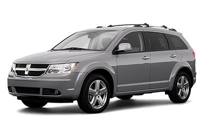
Cigar lighter / power outlet fuses in the Dodge Journey are the fuses M6, M7 and M36 in the engine compartment fuse box.
Table of Contents
Fuse box location

Fuse box diagram

Learn more:
- Featured threads
- Search forums
- RAM TRX Forums
- RAM TRX Talk
OWNERS MANUAL IN PDF
- Thread starter James132006
- Start date Oct 27, 2021

James132006
- Oct 27, 2021
Anybody steer me in the right direction to find or access the owners manual? 2022 preferred, just trying to do some homework on when I get mine. Thanks
I found it, googling it

TRX Fanatic
Lets see if this works. https://msmownerassets.z13.web.core.windows.net/assets/publications/en-us/Ram/2022/1500_DT/P129627_22_DT_OM_EN_USC_DIGITAL.pdf

At a quick glance this seems to cover all models except the TRX, unless I missed something looking through the TOC. Does the TRX have its own manual, or is it incorporated into the general Ram 1500 manual?
That works thanks "eh"

Living The Dream

- Nov 13, 2021
Garrett Bobby Ferguson said: https://www.google.com/url?q=https://www.fcacanada.ca/owners/en/manuals/2021/21_DT_TRX_SU_EN.pdf&sa=U&ved=2ahUKEwiZntD51erzAhUFCs0KHc16DC0QFnoECAAQAg&usg=AOvVaw3-D0qE4w0bWEBPwMJWoD1O It's Canadian, but if you delete "eh" "buddy" "friend" and "guy" used throughout, it should apply to the States. Click to expand...

- Feb 24, 2024
Great forum really helpful I ordered AWE exhaust and Eibach springs front and rear And the S&B Air intake really excited to build the truck. Thank everybody for the awesome post….

- Feb 25, 2024
By the way, do u have service manual ?

2022 RAM 1500 manual: https://msmownerassets.z13.web.core...2/1500_DT/P129627_22_DT_OM_EN_USC_DIGITAL.pdf 2022 RAM TRX manual (attached)
Attachments
- 2022 RAM TRX Manual.pdf 5.4 MB · Views: 27

- Feb 26, 2024
Richmond said: By the way, do u have service manual ? Click to expand...
Tom488 said: Service manuals no longer exist in .PDF, as of about 2007 or so. And as of last year, they no longer exist in USB format, either. They are only available via online subscription. Click to expand...
TRX Forum Favs 👍

TRX Forum Images

Latest Discussions...
- Latest: Air’d outSRT
- Today at 2:34 AM
- Latest: RAMTRX99999
- Today at 2:06 AM
- Latest: TRX_SAV
- Today at 1:28 AM
- Latest: Jakerx
- Today at 1:02 AM
- Latest: SCARd4Life
- Yesterday at 11:36 PM
RAM-TRX Vendors

Follow along with the video below to see how to install our site as a web app on your home screen.
Note: This feature may not be available in some browsers.
Journey’s End Games
Spend $35.00 more and get free shipping!
Your cart is empty
Use this bar to show information about your cookie policy.

Your CCG Headquaters
Welcome to your Journey's End

Spicy Singles

Free tracked shipping on orders over $35 within the US
Satisfaction with every transaction
Fast, Reliable Support
Secure payments
- Opens in a new window.
- Body Controls
- Climate Controls
- Information Displays
- Instrument Clusters
- Power Locks/Kits
- Power Roofs
- Power Seats
- Power Steering
- ABS Modules
- ABS Module Bolt Kit
- Engine Control (ECU/ECM)
- Throttle Bodies / Kits
- Transmission Control (TCM)
- ALL PRODUCTS
- Testimonials & Reviews
- Top 5 Reasons to choose us
- How This Works
- Auto Shop Discounts
FIND YOUR MODULE

- Type Select Type ATV/UTV Car/Truck Motorcycle RV
- Year Select Year
- Make Select Make
- Model Select Model

WE REBUILD AUTO ELECTRONICS.
ABS Control Module Rebuilds

Instrument Cluster Rebuilds

Climate Control Module Rebuilds

Power Accessory Module Rebuilds

Powertrain Module Rebuilds

All Products

Popular Rebuilds

We are a team of electrical engineers and technicians who remanufacture automotive electronics. When your ABS light comes on, or your temperature controls stop working we can help. If the mechanic quotes you a high replacement cost, or you just can't find the part anymore check out our website for a low cost, sustainable alternative. You can remove the part and ship it to us yourself or ask your mechanic to do it for you. Still have questions? Give us a call, we're happy to help!

Seriously into modules since 2004
From its humble beginnings in 2004 operating out of his parent’s tiny pump house, Gavin Curtis grew ModuleMaster into a leading-edge technology company specializing in the repair of automotive electronics. Today, ModuleMaster operates out of two state-of-the-art facilities in Moscow, Idaho, home of the University of Idaho.
ModuleMaster receives over 1,000 modules a month including ABS controllers, instrument clusters, climate control modules, trip computers, and the list keeps growing.
Customer Testimonials
I have used module master on 2 occasions for my 2004 Chevy Suburban. The first time for the ABS module and the second time for the instrument cluster. In both cases both were repaired and returned quickly, both worked perfectly. I recommend module master without any reservations! Mike D. / Long Beach, CA
I sent Module Masters an instrument cluster to get repaired that had an ignition off draw which was not the normal gauge problems that GM clusters have. They fixed it and rebuilt it and it is working great now. I couldn’t be happier!! They have great communication and very knowledgeable. THANKS!! Jesse K. / K-Tech Automotive
You folks have found the right blend of customer service and quality workmanship at a reasonable price. American trained craftsmen are the only way to go for us in this segment of the auto parts repair industry. ABS Automotive | San Mateo, CA
My motorcycle ABS unit quit. Bought a used one off the web, sent to Module Master, they sent it back with the note that it was in perfect working order with NO Charge. I installed it and it works! How wonderful to experience old school customer service, honesty, and integrity. I am sending the faulty one for repair today! Awesome! Wonderful! Stuart D. | Atlanta, GA
Just a short note to thank Gavin and his team at Module Masters. Just received my second front seat ECU module for my Bentley, fully restored to original operating condition. Incredibly fast service and a massive saving over new factory parts, I literally saved hundreds of dollars!! I highly recommend Module Master and will certainly use their services again for future projects. Ken W.
Get in touch with us
2006 S Main St
Moscow, Idaho 83843
Mon - Thurs, 8am - 4pm PST
(208) 892-0764
Organizations & Accreditations
IMAGES
VIDEO
COMMENTS
Starter replacement 2010 Dodge Journey 3.5L. If you are wondering how to install or remove or replace a part on your car, I hope this video will help show y...
Buy Now!New Starter from 1AAuto.com http://1aau.to/ia/1AEST00527The starter is a powerful electric motor that gets your engine to turn over when you turn the...
How to change starter on the dodge journey
I've been having issues starting my 2010 Journey ( 2WD 6 cyl, 3.5 L, Automatic 6-spd) and I'm convinced it may be a bad starter. I replaced the battery in January and just replaced the alternator a few days ago after my car would not start and a horrible smell permeated through the vents when attempting to start multiple times.
14mm Wrench. 14mm Socket. 15mm Socket. 16mm Socket. 18mm Socket. Floor Jack. Copy URL. This video shows you how to install a new starter on your 2009-2020 Dodge Journey.
1. Weak Battery. If your Journey's engine won't crank or cranks very slowly, then the most likely culprit is weak or dead 12v battery. Investigating more closely and doing a battery voltage test will clarify whether the starting problem is due to the battery. A test can be done to measure the voltage between the battery poles, check the ...
located on the DVD, and various customer-oriented documents. Please take the time to read these publica-tions carefully. Following the instructions and recom-mendations in this manual will help assure safe and enjoyable operation of your vehicle. NOTE: After you read the manual, it should be stored in the vehicle for convenient referencing and ...
View and Download Dodge 2010 Journey owner's manual online. Dodge 2010 Journey Owner's Manual. 2010 Journey automobile pdf manual download. ... This VIN Location number also appears on the Automobile Information NOTE: It is illegal to remove or alter the VIN. ... The starter motor will continue to run, and it will disengage automatically when ...
Steps to Remove the Starter in a 3.6 Grand Caravan. Because Dodge used this engine in a ton of different models ranging from cars like the Dodge Avenger to SUV's like the Journey and minivans like the Grand Caravan and Town & Country, the process to remove the starter may vary slightly.
Noises coming from the starter and the vehicle itself not starting are the most common symptoms of a bad starter in your Journey. 1. Noises. Your ears are the best diagnostic tool that you have. You can tell a lot about what's going on with a vehicle by carefully listening for changes. A bad starter will often click, but not engage the ...
The average cost for a Dodge Journey Starter Replacement is between $321 and $445. Labor costs are estimated between $114 and $144 while parts are priced between $207 and $301. This range does not include taxes and fees, and does not factor in your unique location. Related repairs may also be needed.
If you need a car battery, starter motor, solenoid, alternator, or other starting and charging system parts, O'Reilly Auto Parts carries the right parts to help you make a lasting repair and keep you on the road. Shop for the best Starter for your 2010 Dodge Journey, and you can place your order online and pick up for free at your local O ...
Genuine Dodge OEM part designed for your make, model, and year Crafted from premium-quality materials for long-lasting service. $6.34 - $247.40. Dodge OE Electrical - Starter (3.5L) 0. # 2748199134. Dodge Journey 3.5L 2010, Electrical - Starter by Dodge OE.
Dodge Journey not starting? Do you hear clicking noise? Planning to replace the starter? Make sure to check starter fuse and relay before doing any major wor...
WIRING Starter. Genuine Mopar Parts, the Right Choice. MoparPartsGiant .com offers the wholesale prices for genuine 2010 Dodge Journey parts. Parts like Starter & Related Parts are shipped directly from authorized Mopar dealers and backed by the manufacturer's warranty. Parts fit for the following vehicle options. Engine: 4 Cyl 2.4L, 6 Cyl 3.5L.
2010 Dodge Journey R/T 3.5L V6 - Gas Catalog; New Vehicle; Search All Vehicles; Clear Recent Vehicles; Search Bar 4. Search by Part Number(s), Keywords, or VIN.
2010 Dodge Journey Starter Relay; 2010 Dodge Journey Alternator Pulley; 2010 Dodge Journey Neutral Safety Switch; 2010 Dodge Journey Battery Tray - OE Exact Fit; 2010 Dodge Journey Auto Choke / Shutdown Relay; Show Less. Related Makes. Buick Starter; Cadillac Starter; Chevrolet Starter; Chrysler Starter; Ford Starter;
Advertisements. In this article, we consider the first-generation Dodge Journey before a facelift, which was produced from 2009 to 2010. Here you will find fuse box diagrams of Dodge Journey 2009 and 2010, get information about the location of the fuse panels inside the car, and learn about the assignment of each fuse (fuse layout).
In today's video I have a 2011 Dodge Journy with 2.4L that came in with a starting problem, No crank no start. I will show you ... what's up guys? welcome back. In today's video I have a 2011 ...
Verify that your Totally Integrated Power Module (TIPM) matches the product photo. Remove your TIPM. Carefully pack and ship it to us - Instructions. We rebuild it and ship it back to you. Re-install your TIPM.
Thread starter James132006; Start date Oct 27, 2021; James132006 ... Sep 21, 2021 Messages 25 Reaction score 23 Location WI Current Ride Audi A6 Military GySgt USMC Retired. Oct 27, 2021 #1 Anybody steer me in the right direction to find or access the owners manual? 2022 preferred, just trying to do some homework on when I get mine ...
Your trust means a lot to us. At Journey's End Games, we go above and beyond to ensure you are completely satisfied with your purchase. Contact us to get in touch! [email protected]. 208-874-0067. Hours: Mon - Sat 1pm - 9pm (Pacific Standard Time)
Get in touch with us. 2006 S Main St. Moscow, Idaho 83843. USA. Mon - Thurs, 8am - 4pm PST. (208) 892-0764. Module rebuilds for darn near everything: ABS Modules, Climate Control Modules, Instrument Clusters, Power Accessories, Powertrain modules and more.