

Suggested Searches
- Climate Change
- Expedition 64
- Mars perseverance
- SpaceX Crew-2
- International Space Station
- View All Topics A-Z
Humans in Space
Earth & climate, the solar system, the universe, aeronautics, learning resources, news & events.
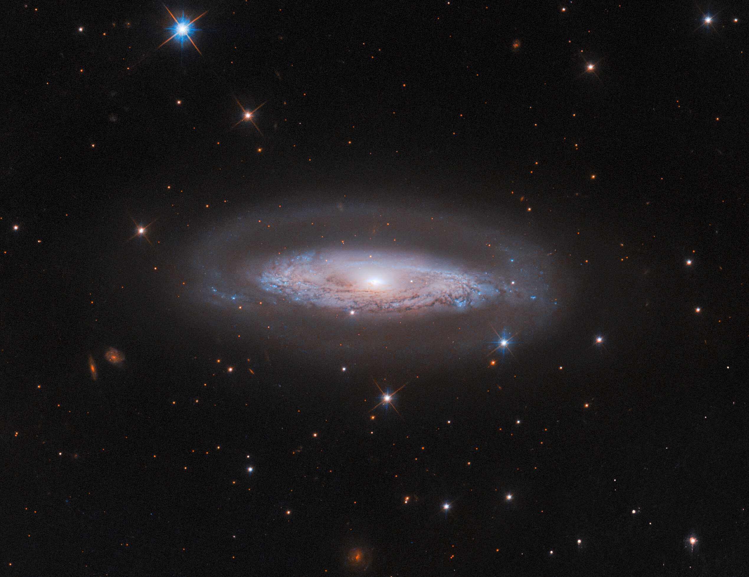
Hubble Examines a Busy Galactic Center
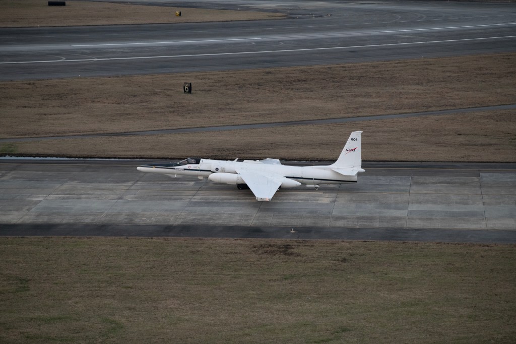
NASA Earth Scientists Take Flight, Set Sail to Verify PACE Satellite Data

What’s Up: September 2024 Skywatching Tips from NASA
- Search All NASA Missions
- A to Z List of Missions
- Upcoming Launches and Landings
- Spaceships and Rockets
- Communicating with Missions
- James Webb Space Telescope
- Hubble Space Telescope
- Why Go to Space
- Commercial Space
- Destinations
- Living in Space
- Explore Earth Science
- Earth, Our Planet
- Earth Science in Action
- Earth Multimedia
- Earth Science Researchers
- Pluto & Dwarf Planets
- Asteroids, Comets & Meteors
- The Kuiper Belt
- The Oort Cloud
- Skywatching
- The Search for Life in the Universe
- Black Holes
- The Big Bang
- Dark Energy & Dark Matter
- Earth Science
- Planetary Science
- Astrophysics & Space Science
- The Sun & Heliophysics
- Biological & Physical Sciences
- Lunar Science
- Citizen Science
- Astromaterials
- Aeronautics Research
- Human Space Travel Research
- Science in the Air
- NASA Aircraft
- Flight Innovation
- Supersonic Flight
- Air Traffic Solutions
- Green Aviation Tech
- Drones & You
- Technology Transfer & Spinoffs
- Space Travel Technology
- Technology Living in Space
- Manufacturing and Materials
- Science Instruments
- For Kids and Students
- For Educators
- For Colleges and Universities
- For Professionals
- Science for Everyone
- Requests for Exhibits, Artifacts, or Speakers
- STEM Engagement at NASA
- NASA's Impacts
- Centers and Facilities
- Directorates
- Organizations
- People of NASA
- Internships
- Our History
- Doing Business with NASA
- Get Involved
NASA en Español
- Aeronáutica
- Ciencias Terrestres
- Sistema Solar
- All NASA News
- Video Series on NASA+
- Newsletters
- Social Media
- Media Resources
- Upcoming Launches & Landings
- Virtual Guest Program
- Image of the Day
- Sounds and Ringtones
- Interactives
- STEM Multimedia

NASA Invites Social Creators to Experience Launch of Europa Clipper Mission
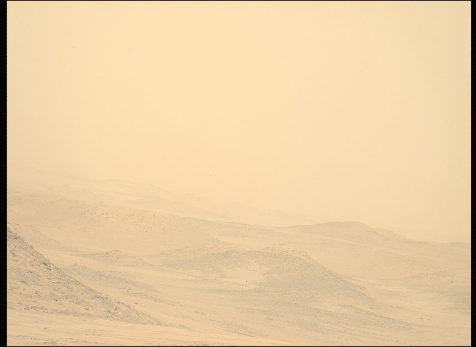
Persevering Through the Storm
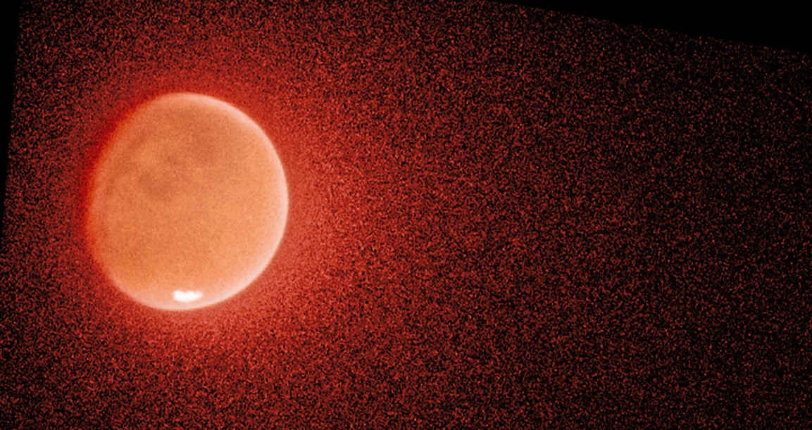
NASA’s Hubble, MAVEN Help Solve the Mystery of Mars’ Escaping Water

NASA Astronaut Don Pettit’s Science of Opportunity on Space Station

NASA, Boeing Optimizing Vehicle Assembly Building High Bay for Future SLS Stage Production
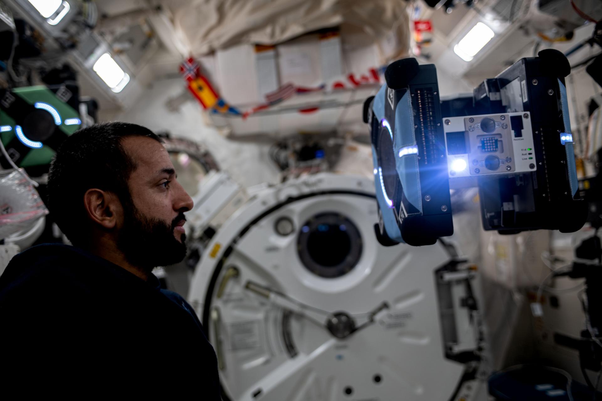
NASA Seeks Input for Astrobee Free-flying Space Robots
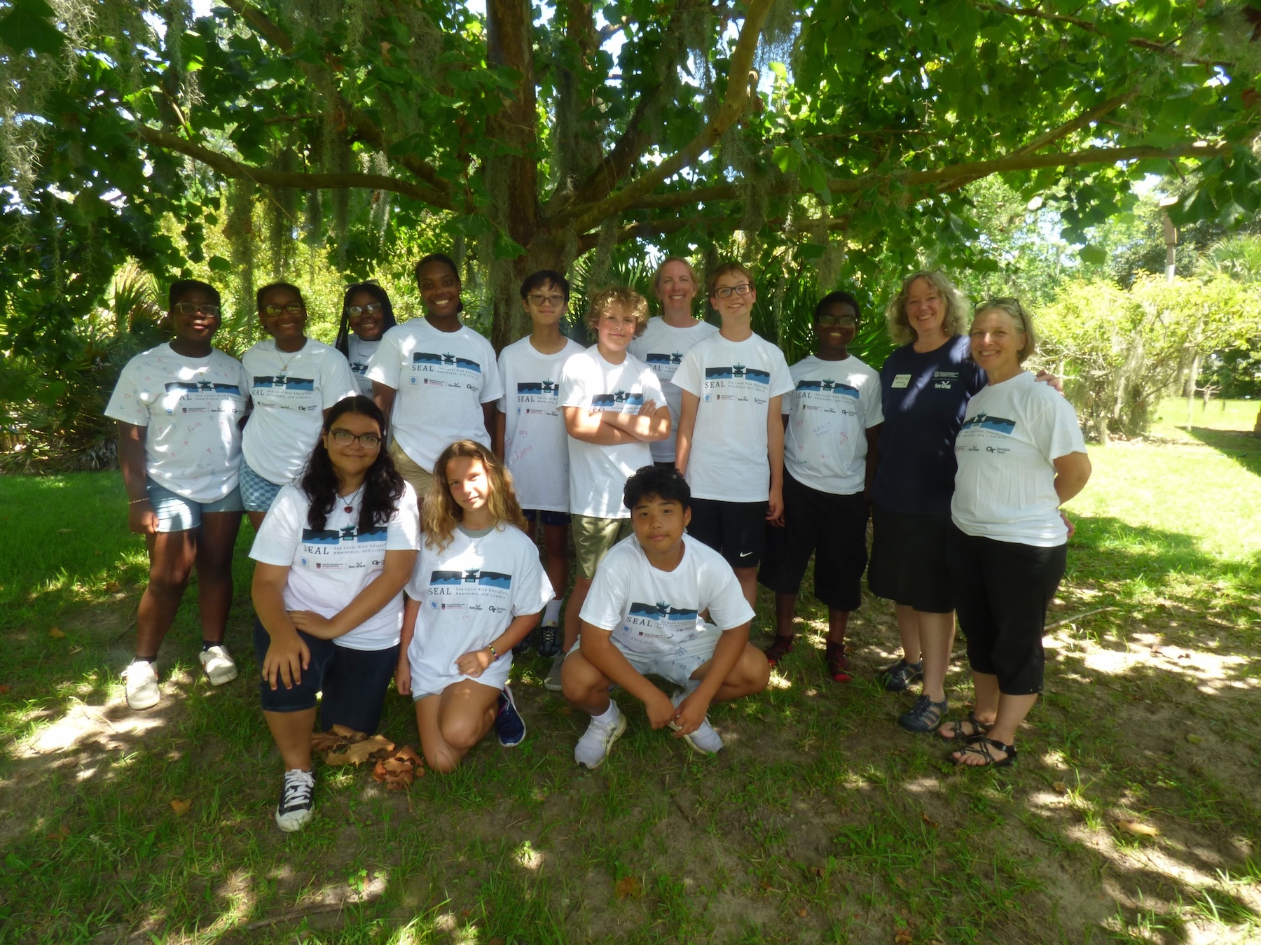
NASA Summer Camp Inspires Future Climate Leaders

NASA Mission Gets Its First Snapshot of Polar Heat Emissions
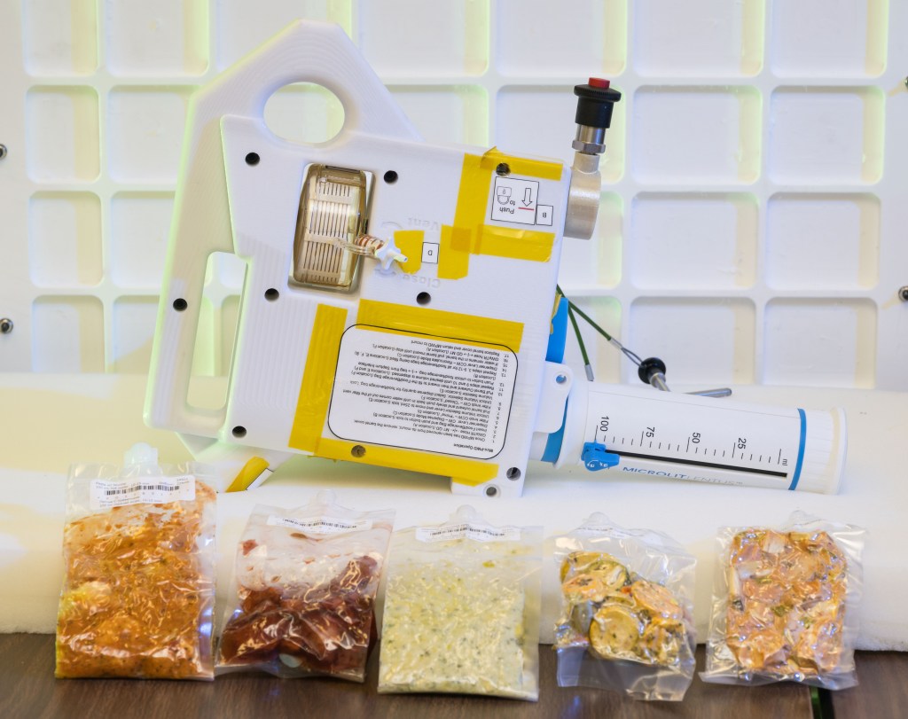
Artemis IV: Gateway Gadget Fuels Deep Space Dining
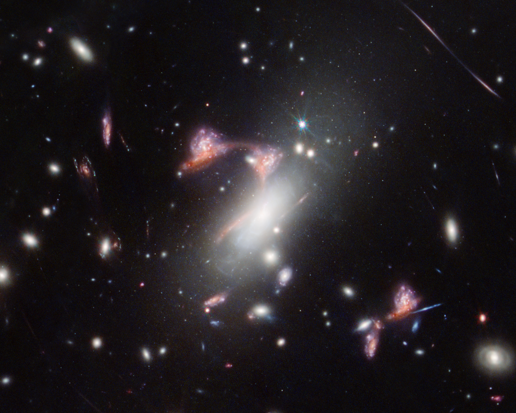
NASA’s Webb Reveals Distorted Galaxy Forming Cosmic Question Mark
NASA’s Mini BurstCube Mission Detects Mega Blast
NASA Tunnel Generates Decades of Icy Aircraft Safety Data

Research Plane Dons New Colors for NASA Hybrid Electric Flight Tests
NASA G-IV Plane Will Carry Next-Generation Science Instrument
OSAM-1 Partnership Opportunity: Request for Information
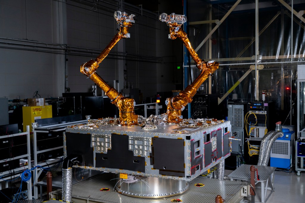
NASA to Support DARPA Robotic Satellite Servicing Program
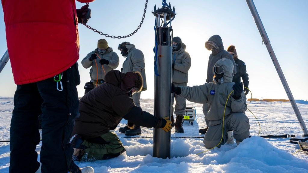
NASA JPL Developing Underwater Robots to Venture Deep Below Polar Ice
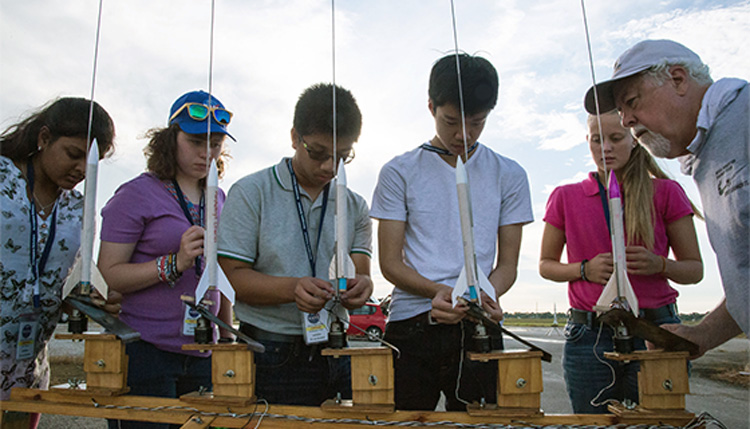
Learn Math with NASA Science

Eclipses Create Atmospheric Gravity Waves, NASA Student Teams Confirm

La NASA invita a los medios al lanzamiento de Europa Clipper

El X-59 de la NASA avanza en las pruebas de preparación para volar

La NASA invita a creadores de las redes sociales al lanzamiento de la misión Europa Clipper
Voyager 2 image of neptune.

This picture of Neptune was produced from the last whole planet images taken through the green and orange filters on the Voyager 2 narrow angle camera. The images were taken at a range of 4.4 million miles from the planet, 4 days and 20 hours before closest approach. The picture shows the Great Dark Spot and its companion bright smudge; on the west limb the fast moving bright feature called Scooter and the little dark spot are visible. These clouds were seen to persist for as long as Voyager’s cameras could resolve them. North of these, a bright cloud band similar to the south polar streak may be seen.
Image Credit: NASA/JPL
Last updated: 24 September 2015

Voyager 1 and 2: The Interstellar Mission

An image of Neptune taken by the Voyager 2 spacecraft. Image credit: NASA
NASA has beautiful photos of every planet in our solar system. We even have images of faraway Neptune , as you can see in the photo above.
Neptune is much too distant for an astronaut to travel there with a camera. So, how do we have pictures from distant locations in our solar system? Our photographers were two spacecraft, called Voyager 1 and Voyager 2!

An artist’s rendering of one of the Voyager spacecraft. Image credit: NASA
The Voyager 1 and 2 spacecraft launched from Earth in 1977. Their mission was to explore Jupiter and Saturn —and beyond to the outer planets of our solar system. This was a big task. No human-made object had ever attempted a journey like that before.
The two spacecraft took tens of thousands of pictures of Jupiter and Saturn and their moons. The pictures from Voyager 1 and 2 allowed us to see lots of things for the first time. For example, they captured detailed photos of Jupiter's clouds and storms, and the structure of Saturn's rings .

Image of storms on Jupiter taken by the Voyager 1 spacecraft. Image credit: NASA
Voyager 1 and 2 also discovered active volcanoes on Jupiter's moon Io , and much more. Voyager 2 also took pictures of Uranus and Neptune. Together, the Voyager missions discovered 22 moons.
Since then, these spacecraft have continued to travel farther away from us. Voyager 1 and 2 are now so far away that they are in interstellar space —the region between the stars. No other spacecraft have ever flown this far away.
Where will Voyager go next?
Watch this video to find out what's beyond our solar system!
Both spacecraft are still sending information back to Earth. This data will help us learn about conditions in the distant solar system and interstellar space.
The Voyagers have enough fuel and power to operate until 2025 and beyond. Sometime after this they will not be able to communicate with Earth anymore. Unless something stops them, they will continue to travel on and on, passing other stars after many thousands of years.
Each Voyager spacecraft also carries a message. Both spacecraft carry a golden record with scenes and sounds from Earth. The records also contain music and greetings in different languages. So, if intelligent life ever find these spacecraft, they may learn something about Earth and us as well!

A photo of the golden record that was sent into space on both Voyager 1 and Voyager 2. Image credit: NASA/JPL-Caltech
More about our universe!

Where does interstellar space begin?

Searching for other planets like ours

Play Galactic Explorer!
If you liked this, you may like:
- Become A Member
- Gift Membership
- Kids Membership
- Other Ways to Give
- Explore Worlds
- Defend Earth
How We Work
- Education & Public Outreach
- Space Policy & Advocacy
- Science & Technology
- Global Collaboration
Our Results
Learn how our members and community are changing the worlds.
Our citizen-funded spacecraft successfully demonstrated solar sailing for CubeSats.
Space Topics
- Planets & Other Worlds
- Space Missions
- Space Policy
- Planetary Radio
- Space Images
The Planetary Report
The exoplanet issue.
The expanding frontier of discovery.
Get Involved
Membership programs for explorers of all ages.
Get updates and weekly tools to learn, share, and advocate for space exploration.
Volunteer as a space advocate.
Support Our Mission
- Renew Membership
- Society Projects
The Planetary Fund
Accelerate progress in our three core enterprises — Explore Worlds, Find Life, and Defend Earth. You can support the entire fund, or designate a core enterprise of your choice.
- Strategic Framework
- News & Press

The Planetary Society
Know the cosmos and our place within it.
Our Mission
Empowering the world's citizens to advance space science and exploration.
- Explore Space
- Take Action
- Member Community
- Account Center
- “Exploration is in our nature.” - Carl Sagan
Bruce Murray Space Image Library
Voyager 2 view of Neptune
This image was constructed using orange, green and synthetic violet (50/50 blend of green filter and UV filter images) taken between 626 and 643 UT.
For full functionality of this site it is necessary to enable JavaScript. Here are instructions on how to enable JavaScript in your web browser .

Daily Visual 20.08.15: Voyager 2 and the Golden Record
On this day in 1977, the Voyager 2 space probe was launched by NASA. It was developed as part of the Voyager program, which saw two identical probes sent to study the outer Solar System and eventually interstellar space.
The unmanned crafts – each weighing 721.9 kg at launch, with a power of 420 watts, and communicating by means of a 3.7-metre parabolic high-gain antenna – were launched from Cape Canaveral, Florida. After Voyager 2’s ascent on 20 August, Voyager 1 was launched a couple of weeks later, on 5 September.
The probes were initially sent on what was conceived as a ‘Planetary Grand Tour’, to cover the giant outer planets of Jupiter, Saturn, Uranus, and Neptune. These planets were due to align at the end of the 1970s, an event which would not recur for another 175 years.
Though Voyager 2 was launched first, Voyager 1 was sent at a different trajectory and sooner reached Jupiter and Saturn. Voyager 1 passed through the Jovian system in 1979, and the Saturnian system in 1980 – thus completing its primary mission, after which it embarked for Titan, Saturn’s largest moon.
Voyager 2’s primary mission came to a conclusion at the close of 1989, after it had encountered the Jovian system in 1979, the Saturnian system in 1981, the Uranian system in 1986, and the Neptunian system in 1989. Voyager 2 remains the only space craft to have visited the outer planets of Uranus and Neptune.
After opting, on the basis of scientific value and calculated risk, to send Voyager 1 by Titan rather than towards Pluto, beyond 1989 Voyager 2’s trajectory could not be altered to make it pass what was still then considered the ninth planet from the sun. Pluto therefore remained unexplored until the New Horizons spacecraft passed by it and its five moons, on 14 July 2015.
Voyager 2 has now been in operation for precisely 38 years. The Deep Space Network continues to receive its data transmissions. Along with Voyager 1, it is expected to keep sending weak radio messages until at least 2025.
At a distance of 108 AU (1.62×10 10 km) from the Sun, and moving at a velocity of 15.4 km/s, Voyager 2 is one of the most distant man-made objects from Earth: accompanied by Voyager 1, and by Pioneer 10 and Pioneer 11, which embarked in 1972 and 1973 on earlier missions to the asteroid belt, Jupiter, and Saturn. Voyager 1 is currently the farthest man-made object from Earth, becoming on 25 August 2012 the first to enter interstellar space.
Both Voyager space probes carry aboard the Voyager Golden Record. The contents of this phonograph record were selected for NASA by a committee chaired by the prominent astronomer and astrophysicist Carl Sagan.
Together Sagan and committee members selected 115 images (although they were forbidden, after controversy over the Pioneer plaques, to send any nudity); an array of natural sounds, from volcanoes to wild dogs to the brainwaves of Sagan’s partner Ann Druyan; a medley of varied musical compositions; greetings in 55 languages both modern and ancient; and printed messages from then-US President Jimmy Carter and UN Secretary-General Kurt Waldheim. Carter’s message states:
‘This is a present from a small, distant world, a token of our sounds, our science, our images, our music, our thoughts and our feelings. We are attempting to survive our time so we may live into yours. We hope someday, having solved the problems we face, to join a community of galactic civilizations. This record represents our hope and our determination, and our good will in a vast and awesome universe.’
Each Golden Record is encased in a protective aluminum jacket, together with a cartridge and needle. Symbolic instructions indicate how the enclosed record should be played. But if the size of the probes and the chances of reaching a suitable audience are small, still the Golden Record is as much a celebration of the diversity of life on Earth.
The selection of music on the Golden Record plays for ninety minutes. The pieces included are as follows:
Carl Sagan had originally requested permission to include ‘Here Comes the Sun’, from the Beatles’ 1969 album Abbey Road . However EMI had concerns over copyright, and denied the request.
The great field recorder and musicologist Alan Lomax was one of Sagan’s main consultants when it came to choosing the music on the Golden Record. Aside from the blues, jazz, and rock music of Blind Willie Johnson, Louis Armstrong, and Chuck Berry, Lomax was responsible for much of the record’s scope: forwarding among other things Peruvian panpipes; a polyphonic Pygmy girls’ initiation song from Zaire; an Azerbaijani mugham performed by Kamil Jalilov; and a Bulgarian folk song, with traditional bagpipes, sung by Valya Balkanska. Sagan wrote that Lomax:
‘was a persistent and vigorous advocate for including ethnic music even at the expense of Western classical music. He brought pieces so compelling and beautiful that we gave in to his suggestions more often than I would have thought possible. There was, for example, no room for Debussy among our selections, because Azerbaijanis play bagpipe-sounding instruments and Peruvians play panpipes and such exquisite pieces had been recorded by ethnomusicologists known to Lomax.’

Björk – Vulnicura

Daily Visual 23.09.15: The Death of Yogi Berra

Joni Mitchell’s Blue Turns Fifty
Your email address will not be published. Required fields are marked *
Privacy Overview

Voyager 1 & 2
Instruments.
The identical Voyager spacecraft are three-axis stabilized systems that use celestial or gyro referenced attitude control to maintain pointing of the high-gain antennas toward Earth. The prime mission science payload consisted of 10 instruments (11 investigations including radio science).
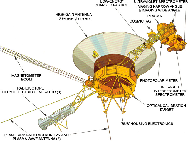
'Bus' Housing Electronics
The basic structure of the spacecraft is called the "bus," which carries the various engineering subsystems and scientific instruments. It is like a large ten-sided box, which can be seen in the Voyager diagram. The centerline of the bus is called the z-axis (and thus the High Gain Antenna) points to Earth. The spacecraft is designed to roll about this axis by firing small thrusters which are attached to the bus.
Each of the ten sides of the bus contains a compartment (a bay) that houses various electronic assemblies. Bay 1, for example, contains the radio transmitters. The bay are numbered 1 to 10 (numbered clockwise as seen from Earth).
Cosmic Ray Subsystem (CRS)
The CRS looks only for very energetic particles in plasma, and has the highest sensitivity of the three particle detectors. Very energetic particles can often be found in the intense radiation fields surrounding some planets (like Jupiter). Particles with the highest-known energies come from other stars. The CRS looks for both.
The CRS makes no attempt to slow or capture the super-energetic particles. They simply pass completely through the CRS. However, in passing through, the particles leave signs that they were there.
Cosmic Ray Subsystem Science Objective
- To measure the energy spectrum of electrons from 3 - 110 MeV.
- To measure the energy spectra and elemental composition of all cosmic ray nuclei from hydrogen through iron over an energy range from approximately 1 - 500MeV/nuc.
- To provide information on the energy content, origin, acceleration process, life history, and dynamics of cosmic rays in the galaxy, and contribute to an understanding of the nucleosynthesis of elements in cosmic ray sources.
- To provide information on the transport of cosmic rays, Jovian electrons, and low energy interplanetary particles over an extended region of interplanetary space.
- To measure the three-dimensional streaming patterns of nuclei from Hydrogen through Iron and electrons over an extended range.
- To measure particle charge compostion in the magnetosphere of Jupiter, Saturn, Uranus, and Neptune.
Principal Investigator
Edward C. Stone California Institute of Technology 289 Cahill Astrophysics
M/S 290-17 Pasadena, CA 91125 [email protected]
High-Gain Antenna
The HGA transmits data to Earth on two frequency channels (the downlink). One, at about 8.4 gigahertz (8,400 million cycles per second), is the X-band channel and contains science and engineering data. For comparison, the FM radio band is centered around 100 megahertz. The X-band downlink science data rates are as high as 7.2 kilobits per second. The other channel, around 2.3 gigahertz, is in the S-band, and contains only engineering data on the health and state of the spacecraft at the low rate of 40 bits per second. S-band has not been used since the last planetary encounter.
Imaging Science Subsystem (ISS)
The ISS is a modified version of the slow scan vidicon camera designs that were used in the earlier Mariner flights. The ISS consists of two television-type cameras, each with 8 filters in a commandable Filter Wheel mounted in front of the vidicons. One has a low resolution 200 mm wide-angle lens with an aperture of f/3, while the other uses a higher resolution 1500 mm narrow-angle f/8.5 lens.
Unlike the other onboard instruments, operation of the cameras is not autonomous, but is controlled by an imaging parameter table residing in one of the spacecraft computers, the Flight Data Subsystem (FDS).
Imaging Science Subsystem Objectives
- Observe and characterize the circulation of the planetary atmosphere, provide limits on atmospheric composition, and determine the wind velocities in the regions observed.
- Map the radial and azimuthal distribution of material in the ring plane; search for new rings.
- Obtain global multi-spectral coverage of all satellites; establish rotation rates and spin axis orientations, study the surface morphology of Triton at spatial resolutions less than 2 km; search for undiscovered satellites.
- Provide support images to assist other onboard investigations in their data reduction.
Infrared Interferometer Spectrometer and Radiometer (IRIS)
The IRIS actually acts as three separate instruments. First, it is a very sophisticated thermometer. It can determine the distribution of heat energy a body is emitting, allowing scientists to determine the temperature of that body or substance. Second, the IRIS is a device that can determine when certain types of elements or compounds are present in an atmosphere or on a surface. Third, it uses a separate radiometer to measure the total amount of sunlight reflected by a body at ultraviolet, visible, and infrared frequencies.
The Infrared Interferometer Spectrometer and Radiometer measures radiation in two regions of the infrared spectrum, from 2.5 to 50μm and from 0.3 to 2.0μm.
Infrared Interferometer Spectrometer and Radiometer Objective
- Determination of atmospheric vertical thermal structure (which in turn aids modeling of atmosphereic dynamics).
- Measurement of the abundances of hydrogen and helium (as a check on theories regarding their ratio in the primitive solar nebula).
- Determination of the balance of energy radiated to that absorbed from the sun (to help investigate planetary origin, evolution, and internal processes).
Low-Energy Charged Particles (LECP)
The LECP looks for particles of higher energy than the PLS, and it overlaps with the Cosmic Ray Subsystem (CRS). It has the broadest energy range of the three sets of particle sensors.
The LECP can be imagined as a piece of wood, with the particles of interest playing the role of bullets. The faster a bullet moves, the deeper it will penetrate the wood. Thus, the depth of penetration measures the speed of the particles. The number of "bullet holes" over time indicates how many particles there are in various places in the solar wind, and at the various outer planets. The orientation of the wood indicates the direction from which the particles came.
The Low-Energy Charged Particle experiment uses two solid-state detector systems mounted on a rotating platform. The two subsystems are the low-energy particle telescope (LEPT) and the low-energy magnetospheric particle analyzer (LEMPA).
Low-Energy Charged Particles (LECP) Objective
- The spectra of the various atomic species comprising the galactic cosmic radiation, especially at low energy.
- Time variation of galactic cosmic rays.
- The radial gradient of galactic cosmic rays.
- Energetic particles of solar origin associated with flares and active regions.
- Energetic particles of planetary origin.
- Interplanetary energetic particles.
Stamatios M. Krimigis Johns Hopkins University Applied Physics Laboratory 11100 John Hopkins Rd. Laurel, MD 20723-6099 [email protected]
Magnetometer (MAG)
Although the MAG can detect some of the effects of the solar wind on the outer planets and moons, its primary job is to measure changes in the Sun's magnetic field with distance and time, to determine if each of the outer planets has a magnetic field, and how the moons and rings of the outer planets interact with those magnetic fields.
Magnetometer (MAG) Objective
- Measure and analytically represent the planetary magnetic fields of Jupiter, Saturn, Uranus, and Neptune.
- Determine the magnetosphere structure of all the giant planets encountered. Investigate the basic physical mechanisms and processes involved both in interactions between the solar wind and the magentosphere and in internal magnetospheric dynamics, in correlative studies with other particles and fields investigations.
- Investigate the interactions of the satellites of these planets with their magnetosphere/solar wind environments.
- Accurately survey the interplanetary magnetic field beyond 1 AU and continue and extend studies of large-scale characteristics of the interplanetary medium.
- Continue and extend studies of the physics of microscale phenomena in the solar wind.
- Search for the transition region between the interplanetary and interstellar media, and if possible, investigate the magnetic characteristics of the boundary region and measure the galactic magnetic field and its variations.
Dr. Adam Szabo NASA Goddard Space Flight Center Code 672 Greenbelt, MD 20771 [email protected]
Optical Calibration Target
The target plate is a flat rectangle of known color and brightness, fixed to the spacecraft so the instruments on the movable scan platform (cameras, infrared instrument, etc.) can point to a predictable target for calibration purposes.
Photopolarimeter Subsystem (PPS)
The Photopolarimeter Subsystem uses a 0.2 m telescope fitted with filters and polarization analyzers. It covers eight wavelengths in the region between 235 nm and 750 nm.
The experiment is designed to determine the physical properties of particulate matter in the atmospheres of Jupiter, Saturn, and the Rings of Saturn by measuring the intensity and linear polarization of scattered sunlight at eight wavelengths in the 2350-7500A region of the spectrum. The experiment will also provide information on the texture and probable composition of the surfaces of the satellites of Jupiter and Saturn and the properties of the sodium cloud around Io. During the planetary encounters a search for optical evidence of electrical discharges (lighting) and auroral activity will also be conducted.
The following two images show the front and side of the PPS instrument.
Planetary Radio Astronomy (PRA)
The Plasma Wave Subsystem and the Planetary Radio Astronomy experiment share the two long antennas which stretch at right-angles to one another, forming a "V". The PWS covers a frequency range of 10 Hz to 56 kHz. The PRA receiver covers two frequency bands, from 20.4 kHz to 1300 kHz and from 2.3 MHz to 40.5 MHz.
Plasma Science (PLS)
The PLS experiment measures the low energy ions and electrons that comprise the bulk of the plasma. Three plasma detectors point in the direction of the Earth to observed solar wind flow and a fourth looks at a right angle to this direction to observed planetary magnetospheres and the heliosphere. It determines the flow speed and direction, density, and temperature of the plasma.
Plasma Science (PLS) Objective
- The properties and radial evolution of the solar wind.
- The interacion of the solar wind with Jupiter, Saturn, Uranus, and Neptune.
- The sources, properties, and morphology of the magnetospheric plasma from Jupiter, Saturn, Uranus, and Neptune.
- The interactions of magnetospheric plasma with the planetary satellites with particular emphasis on plasma properties in the vicinity of Io, Titan, and Triton.
- Ions of interstellar origin.
- Detect and characterize the nature of the termination shock, where the solar wind slows down and becomes more dense as it prepares to encounter the heliopause.
- Make the first detection of the heliopause boundary and the first detection of the plasma from outside our solar system, the interstellar medium.
John Richardson Massachusetts Institute of Technology Center for Space Research 77 Massachusetts Avenue Room 37-641 Cambridge, MA 02139 [email protected]
Plasma Wave Subsystem (PWS)
Donald Gurnett University of Iowa Dept. of Physics & Astronomy Iowa City, IA 52242 [email protected]
Radioisotope Thermoelectric Generators (RTGs)
Three radioisotope thermoelectric generator units (RTGs), electrically parallel-connected, are the central power sources for the mission module. Each RTG is made up of a radioisotope heat source , a thermoelectric converter, a gas pressure venting system, temperature transducers, connectors, a heat rejecting cylindrical container, and bracketry. The RTGs are mounted in tandem (end-to-end) on a deployable boom as part of the MM.
The heat source radioisotopic fuel is Plutonium-238 in the form of the oxide Pu02. In the isotopic decay process, alpha particles are released which bombard the inner surface of the container. The energy released is converted to heat and is the source of heat to the thermoelectric converter.
As of 2023, the twin Voyagers' RTGs are in stable operation at 225 We.
Learn More About Radioisotope Power for Spacecraft

Radioisotope Power Systems
Space nuclear power to explore the deepest, dustiest, darkest, and most distant regions of our solar system and beyond.
Ultraviolet Spectrometer (UVS)
The UVS is a very specialized type of light meter that is sensitive to ultraviolet light. It determines when certain atoms or ions are present, or when certain physical processes are going on. The instrument looks for specific colors of ultraviolet light that certain elements and compounds are known to emit.
The Sun emits a large range of colors of light. If sunlight passes through an atmosphere, certain elements and molecules in the atmosphere will absorb very specific frequencies of light. If the UVS, when looking at filtered sunlight, notices the absence of any of these specific colors, then particular elements and/or compounds have been detected. This process is call identifying elements or compounds by atomic absorption.
The Ultraviolet Spectrometer (UVS) covers the wavelength range of 40 nm to 180 nm looking at planetary atmospheres and interplanetary space.
Ultraviolet Spectrometer (UVS) Objective
- To determine the scattering properties of the lower planetary atmospheres.
- To determine the distribution of constituents with height.
- To determine the extent and distribution of hydrogen corona of the planets and satellites.
- To investigate night airglow and auroral activity.
- To determine the UV scattering properties and optical depths of planetary rings.
- To search for emissions from the rings and from any ring "atmosphere."
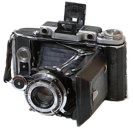
Moskva-2 is a Soviet folding medium format camera with a 6×9 frame format that was produced at the KMZ plant from 1947 to 1956.
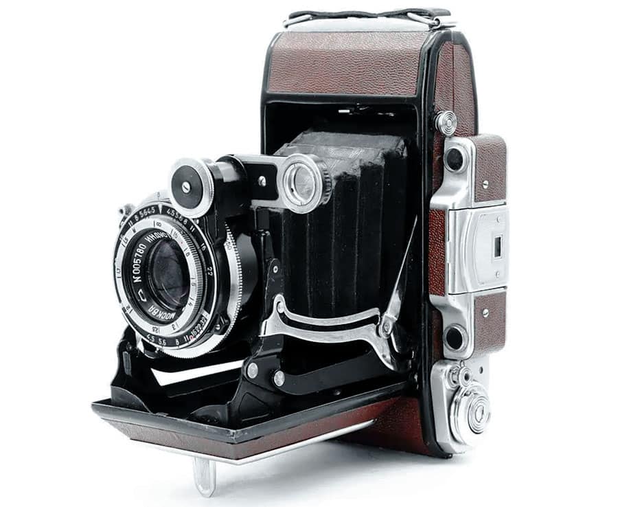
Moskva-2 differs from Moskva-1 in the presence of a rangefinder. This simple device in the camera greatly simplifies all the work and makes the Moskva-2 a camera not only for the collection, but also for real photography.
Moskva-2 Specifications
- Type: medium format rangefinder folding camera
- Manufacturer: KMZ plant
- Production period: 1947-1956
- Format: 6x9cm on 120 film
- Lens mount: fixed lens
- Lens: Industar-23 f4.5/110
- Shutter: leaf shutter with speeds from 1 to 1/250 sec.
- Viewfinder: optical parallax viewfinder not combined with a rangefinder
- Lighmeter: none
- Flash synchronisation: none
- Selftimer: none
- Weight: 854 grams
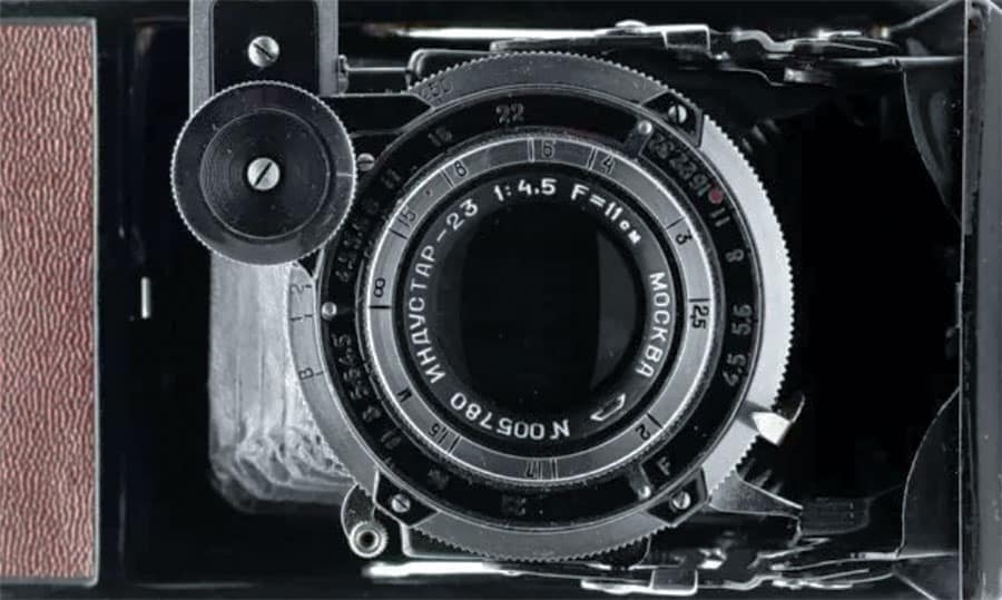
The Moskva-2 camera was produced for some time in parallel with the first model, but in 1949 the production of the Moskva-1 camera was completed due to the fact that this camera was not in great demand in comparison with the Moskva-2 camera.
Both cameras are very similar to each other in many ways. Moskva-1 was copied from Ikonta C 521/2 and Moskva-2 from Super Ikonta C 531/2. As you probably know, the Super prefix on Ikonta cameras indicated the presence of a rangefinder.
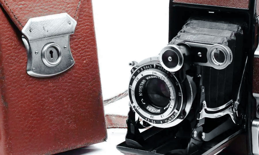
In the 40s, there were practically no full-fledged medium format cameras made in the Soviet Union, especially with a frame size of 6×9. In a market with a complete lack of such cameras, Moskva-2 was a very popular device, especially since the camera was very advanced even by German standards, especially by Soviet ones.
Between 1947 and 1956, 197,640 copies of Moskva-2 were created, and nowadays it is quite easy to find this camera in good condition.
The Moskva-2 camera was equipped with an Industar-23 f4.5/110 lens, which was copied from Tessar f4.5/110. As we said in the article about Moskva-1, the Industar-23 lens is a very good Tessar clone and produces a very beautiful picture with good sharpness and nice bokeh.
The lens has 10 aperture blades, which produces a very round aperture opening at any aperture. The minimum focusing distance is 1.5m. This may seem like too much distance, but keep in mind that this is a rangefinder camera, and at a closer distance, parallax will not allow for proper framing.
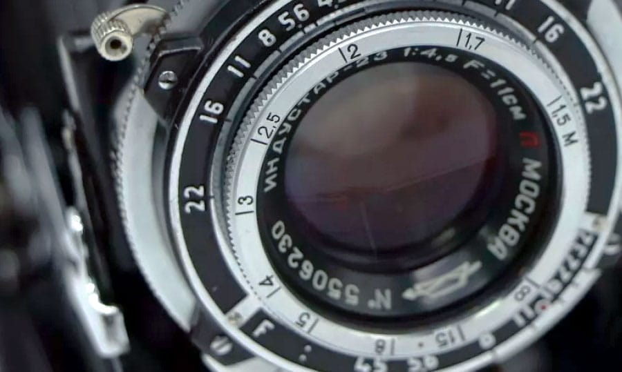
Moskva-2 was equipped with a Moment-1 shutter with shutter speeds from 1 to 1/250 sec. These are very good characteristics for a 6×9 folding camera of the 40s-50s.
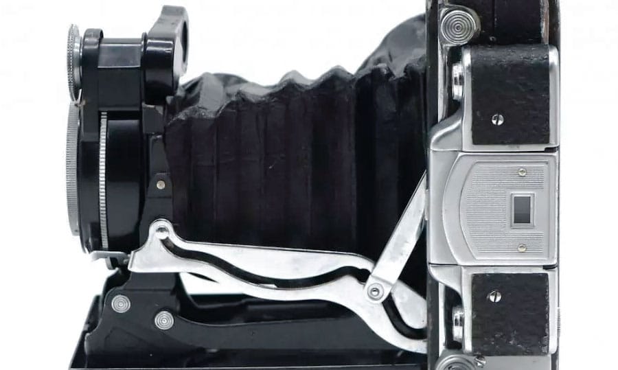
Due to the focal length of 110mm, you can only shoot handheld at shutter speeds of 1/125 and 1/250 sec, and it will be convenient to use all other shutter speeds only with a tripod. The fact that the camera was primarily made to work with a tripod is also evidenced by the fact that Moskva-2 has two tripod sockets. The first is for vertical shooting and the second is for horizontal.
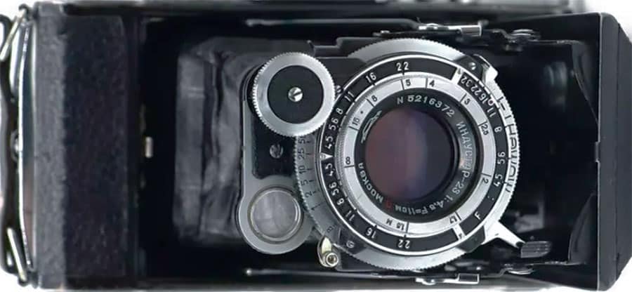
The Moskva-2 camera is very well assembled. When folded, the camera looks like a small brick of complex shape and can fit in a bag or jacket pocket. The camera is made of aluminum alloy and covered with a very nice leatherette.
The Moskva-2 camera does not have a frame counter, and frame control is carried out through a red window on the back of the camera.
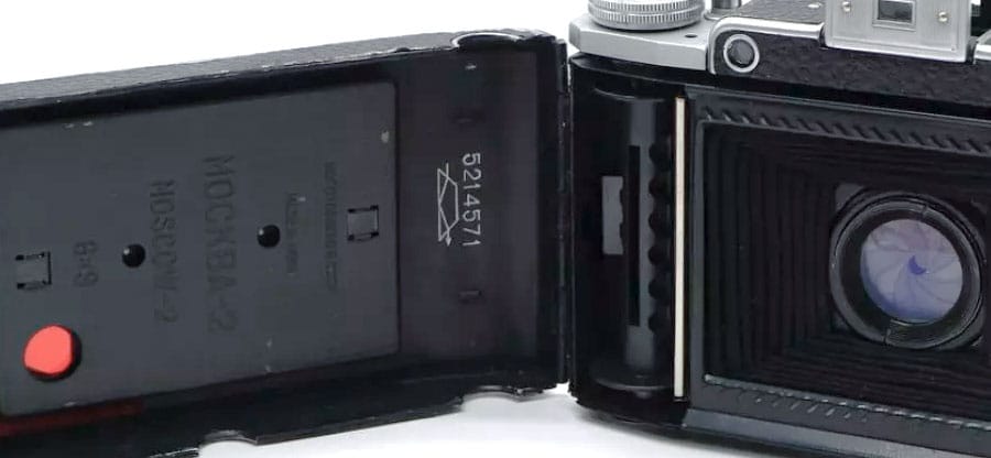
This Soviet film camera has a shutter lock mechanism that protects against double exposure. Once you have pressed the shutter button, it is locked until you turn the film advance knob to a new frame and unlock the shutter button.
But you can double exposure if you want. This is done using a duplicate shutter button located in front of the camera directly below the lens.
Film advance is not combined with shutter cocking. That is, you first advance the film using the knob in the upper part of the body, then cock the shutter using the lever on the lens barrel.
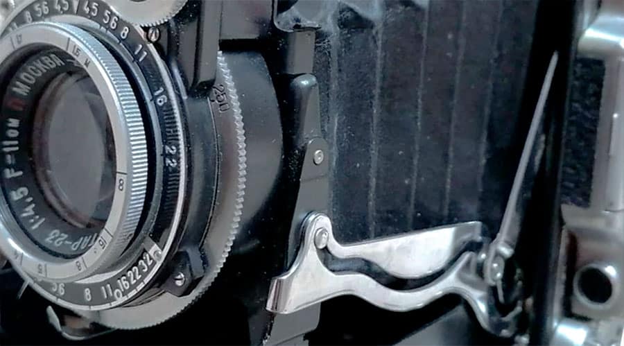
The Moskva-2 camera is much better than the Moskva-1, and you should pay your attention to this camera if you want a 6×9 folding film camera. This camera is very well built, has a very good lens and a decent set of shutter speeds.
In addition, it is outwardly a very beautiful camera and carries a certain flair of cameras from the beginning of the 20th century. Using Moskva-2, you will not only get cool pictures, but also enjoy working with the camera.
MOSKVA-2 PHOTOS

Professional photographer, artist and sculptor. Founder, owner and author of the Soviet Cameras. Has been involved in photography since 2005. Owns a large collection of film cameras and vintage lenses.
Similar Posts
The Best Soviet Cameras
What is ISO
Leave a reply cancel reply.
Your email address will not be published. Required fields are marked *
Save my name, email, and website in this browser for the next time I comment.
The Moskva-2 was a sophisticated rollfilm camera with coupled rangefinder . It was a self-erecting folding camera for type No. 120 film rolls. Its opening button released the front door as well as a two-frame Newton-type viewfinder . Its solid sturdy metal body was covered with soft black leatherette. The camera supported two formats by means of an optional small format frame and a back with two red windows .
The camera had a rangefinder setup similar to that of German Ikonta rangefinder cameras. The special trick to couple it to the focusable lens in the folder's front standard was that its movable part was separated from the rangefinder's body on top of the camera. This separate optical part was mounted on the front standard and had to be unfolded after having unfolded the camera. The little wheel of that separate rangefinder front lens had to be used to adjust distance setting while looking through the rangefinder's ocular . The camera had a 110mm f4.5 lens in a "Moment" shutter for speeds 1 to 1/250 sec plus B mode. The shutter had to be released by pressing the button beside the film advance wheel. The button was locked after exposure until the advance wheel was turned again.
- Moskva-2, -4 and -5 user manual at Butkus.org
- Moskva-2 on Sovietcams.com
- Kozma Prutkoff about Moskva-2 on photo.net
- Flickr image
- 6x9 rangefinder folding
- Soviet cameras
- Image by Alexei Dolganov
Navigation menu
Personal tools.
- View source
- View history
- List of Companies
- Community portal
- Recent changes
- Random page
- What links here
- Related changes
- Special pages
- Printable version
- Permanent link
- Page information
- This page was last edited on 31 December 2021, at 07:17.
- Text is available under GNU Free Documentation License 1.3 ; other licenses apply to photos.
- Privacy policy
- About Camera-wiki.org
- Disclaimers
- Former USSR
- Rangefinder
- Edit source
Moskva-2 type 1 (1947) image by Alexander Komarov
type 1 with early KMZ logo image by Alexander Komarov
The Moskva-2 (Mockba = Moskva means Moscow) is a medium format rollfilm rangefinder folding camera made by KMZ in former USSR and produced between 1947-56 with quantity 197.640 units. This camera is a copy of Zeiss Super Ikonta .
It was a self-erecting foldinng camera for type No. 120 film rolls. Its opening button released the front door as well as a two-frame Newton-type viewfinder . Its solid sturdy metal body was covered with soft black leatherette. The camera supported two formats by means of an optional small format frame and a back with two red windows .
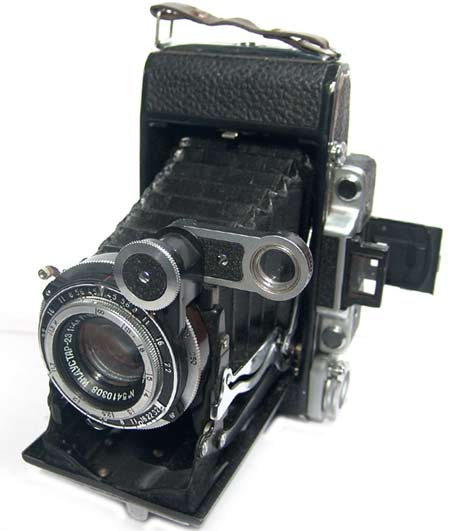
Moskva-2 type 4 (1950-56) image by Alexander Komarov
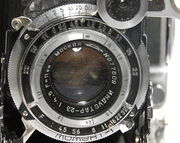
type 4 with new KMZ logo image by Alexander Komarov
The camera had a rangefinder setup similar to that of German Zeiss Super Ikonta rangefinder cameras. The special trick to couple it to the focusable lens in the folder's front standard was that its movable part was separated from the rangefinder's body on top of the camera. This separate optical part was mounted on the front standard and had to be unfolded after having unfolded the camera. The little wheel of that separate rangefinder front lens had to be used to adjust distance setting while looking through the rangefinder's ocular . The shutter had to be released by pressing the button beside the film advance wheel. The button was locked after exposure until the advance wheel was turned again.
There are 5 types and one sub-type of the Moskva-2. [1]
See also the article Moskva .
Some fearures [ ]
- Main difference from the Moskva-1 is the addition of a coupled rangefinder
- Early types have the old KMZ logo then new logo on the lens and body. [2]
- Film: 120 roll, picture size 6x9cm
- Lens: Industar -23 110mm f/4.5
- Aperture: up to f/32
- Focusing: 1.5m to inf
- Shutter: Moment-1 with speeds 1-1/250 +B
- The earliest version, type-1, with Compur shutter with speeds 1-1/400 and imported lens
Notes and references [ ]
- ↑ Typing and some info are as to Alexander Komarov
- ↑ See also the artivle Soviet Factory Logos
- Moskva-2 - Sample Images at www.sample-image.com/
- in Fotoua by Alexander Komarov
- in SovietCams by Aidas Pikiotas
- Krasnogorsk Moskva 2 at www.collection-appareils.fr
- 1 Radioactive lenses
- 2 Helios-44
- 3 Minolta XG series

COMMENTS
Voyager 2: Hello Interstellar Space, Goodbye Heliosphere Full Resolution: TIFF (8.947 MB) JPEG (633.8 kB) 2018-12-10: Voyager Interstellar Mission: 1920x1080x3: PIA22915: Voyager 2 Spacecraft Instruments Full Resolution ...
Regrettably, the camera systems on the Voyager spacecraft were disabled decades ago. This is because they traveled so far out into space that they no longer receive enough light to function as intended. NASA turned off the camera system for Voyager 1 after it took the "Solar System Family Portrait" in 1990, while Voyager 2 took its last photo ...
The Narrow angle Camera (NAC) - 800x800. The Wide Angle Camera (WAC) - 800x800. The Photopolarimeter System (PPS) - One pixel - an EMR 510-E-06 photomultiplier tube (PMT) with a tri-alkali (S-20) photocathode. Data was stored on a digital tape drive and then played back during transmission periods.
The pixel resolution was 1.908 arcseconds. At the closest approach of Voyager 2 to Jupiter (570,000 km), the resolution was about 5.27 km/pixel. The other wide angle camera with 202 mm focal length, a field of view of 3.169 degrees and a theoretical resolution of 2.87 arcseconds. The camera of Juno has 1600 by 1200 pixels, see. Each pixel is ...
Each Voyager camera is unique in terms of its calibrated characteristics. ... The active image area on the target is 11.14 x 11.14 mm. Each frame consists of 800 lines with 800 picture elements (pixels) per line, i.e., 1 pixel =14 microns. ... As of 5/26/88 the Voyager 2 scan platform offset values were updated and the removal of all extraneous ...
NASA's Voyager 2 is the second spacecraft to enter interstellar space. On Dec. 10, 2018, the spacecraft joined its twin - Voyager 1 - as the only human-made objects to enter the space between the stars. Voyager 2 is the only spacecraft to study all four of the solar system's giant planets at close range. Voyager 2 discovered a 14th moon at ...
Voyager 2 - Wikipedia ... Voyager 2
1720x1720x3. PIA18182: Uranus as seen by NASA's Voyager 2. Full Resolution: TIFF (8.879 MB) JPEG (78.82 kB) 1989-10-02. Triton. Voyager. 932x1884x1. PIA14448:
Voyager Spacecraft: Voyager 2 Product Size: 2188 x 2185 pixels ... picture of Neptune was produced from the last whole planet images taken through the green and orange filters on the Voyager 2 narrow angle camera. The images were taken at a range of 4.4 million miles from the planet, 4 days and 20 hours before closest approach. ...
This picture of Neptune was produced from the last whole planet images taken through the green and orange filters on the Voyager 2 narrow angle camera. The images were taken at a range of 4.4 million miles from the planet, 4 days and 20 hours before closest approach. The picture shows the Great Dark Spot and its companion bright smudge; on the ...
Voyager 2 image of the Saturnian satellite Titan from 4.5 million km. The bright southern hemisphere and dark north polar region can be seen, along with visible cloud bands parallel to the equator. ... Instrument: Narrow Angle Vidicon Camera Instrument Resolution (pixels): 800 x 800, 8 bit Instrument Field of View (deg): .424 x .424 Filter ...
Where Are They Now? Both Voyager 1 and Voyager 2 have reached "interstellar space" and each continue their unique journey deeper into the cosmos. In NASA's Eyes on the Solar System app, you can see the actual spacecraft trajectories of the Voyagers updated every five minutes. This simulated view of the solar system allows you to explore the ...
The Voyager 1 and 2 spacecraft launched from Earth in 1977. Their mission was to explore Jupiter and Saturn —and beyond to the outer planets of our solar system. This was a big task. No human-made object had ever attempted a journey like that before. The two spacecraft took tens of thousands of pictures of Jupiter and Saturn and their moons.
Voyager 2 view of Neptune Voyager 2 Narrow Angle Camera image of Neptune taken on August 20, 1989 as the spacecraft approached the planet for a flyby on August 25. The Great Dark Spot, flanked by cirrus clouds, is at center. A smaller dark storm, Dark Spot Jr., is rotating into view at bottom left. Additionally, a patch of white cirrus clouds ...
On this day in 1977, NASA launched Voyager 2 to study the outer Solar System. It carried aboard the Golden Record, with music from Chuck Berry to Bach.
Spacecraft Instruments - Voyager - NASA
700 x 512 pixels (w x h) ... These two 591-second exposures of the rings of Neptune were taken with the clear filter by the Voyager 2 wide-angle camera on Aug. 26, 1989 from a distance of 280,000 kilometers (175,000 miles). The two main rings are clearly visible and appear complete over the region imaged. The time between exposures was one hour ...
Crisp thermal images - 320 x 240 pixels The Voyager II provides crisp, clear thermal imaging, 320 x 240 pixels, in total darkness, smoke and light fog. ... Sony FCB EX-980SP High Telephoto Zoom Color Block Camera (PAL) Effective pixels Approx. 680,000 pixels (NTSC) - approx. 800,000 pixels (PAL) Standard lens performance f=3.5mm (wide) to 91. ...
Moskva-2 is a Soviet folding medium format camera with a 6×9 frame format that was produced at the KMZ plant from 1947 to 1956. Moskva-2 differs from Moskva-1 in the presence of a rangefinder. This simple device in the camera greatly simplifies all the work and makes the Moskva-2 a camera not only for the collection, but also for real photography.
945 x 870 pixels (w x h) ... This photograph of Neptune was reconstructed from two images taken by Voyager 2's narrow-angle camera, through the green and clear filters. The image shows three of the features that Voyager 2 has been photographing during recent weeks. At the north (top) is the Great Dark Spot, accompanied by bright, white clouds ...
Moskva-2. The Moskva-2 was a sophisticated rollfilm camera with coupled rangefinder. It was a self-erecting folding camera for type No. 120 film rolls. Its opening button released the front door as well as a two-frame Newton-type viewfinder. Its solid sturdy metal body was covered with soft black leatherette. The camera supported two formats by ...
1000 x 1000 pixels (w x h) ... (9.2 million miles) on August 14, 1989. It was produced from images taken through the orange, green and violet filters of Voyager's narrow angle camera. As Voyager 2 approaches Neptune, rapidly increasing image resolution is revealing striking new details in the planet's atmosphere, and this picture shows features ...
The Moskva-2 (Mockba = Moskva means Moscow) is a medium format rollfilm rangefinder folding camera made by KMZ in former USSR and produced between 1947-56 with quantity 197.640 units. This camera is a copy of Zeiss Super Ikonta. It was a self-erecting foldinng camera for type No. 120 film rolls. Its opening button released the front door as well as a two-frame Newton-type viewfinder. Its solid ...